


















Lesson 17 of 46 · Shafts and Fasteners
Shafts and Fasteners: The Big Picture
Chapter 4 overview: how rotating shafts, keys, critical speed and bolted joints work together, why bending and fatigue size a shaft, and why preload keeps a joint tight.
Almost every machine has a shaft that turns and a set of fasteners that hold the rest together. They look humble, but they are where the previous three chapters meet. A shaft sees combined bending and torsion, reversing every turn, with stress concentrations at every shoulder and keyway: you need loads, Kt, the Marin factors and the Goodman line to size it. A bolt sees a stress cycle too, but the preload changes the picture completely. In this chapter you will use what you have learned to design both.
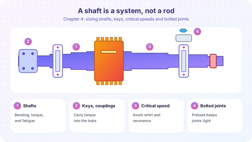
The big picture
- Shafts. Find the loads, draw the shear and moment diagrams, locate the critical section, and size it with the DE-Goodman formula, then check yield, deflection and slope.
- Keys and splines. Transfer torque from shaft to hub. Check shear and bearing, and remember the keyway weakens the shaft.
- Critical speed. A rotating shaft has a natural frequency; running near it causes violent whirling. Stay 20 to 30% away.
- Bolted joints. A preloaded bolt is a spring in parallel with the clamped plates, and it feels only a small fraction
Cof the external load.
Shaft design in five steps
Check the rest
Keys
Critical speed
Bolted joints
How the topics connect
A shaft, a key and a bolted joint look like separate topics, but one problem links them all: how does a force get from where it is applied to where it is carried? A motor turns a coupling, the coupling bolts carry the torque into the shaft, the shaft carries it to a gear through a key, and the gear passes it to a mating gear. At every step a stress concentration appears, and at every step a different failure is possible: the shaft can fatigue at a shoulder, the key can crush on its side, the bolts can lose preload and the whole shaft can whirl if it turns too close to its natural frequency.
The design therefore follows the load path, just as the load-path picture in chapter 2 showed. You size the shaft for fatigue, because bending reverses every turn. You then pick the key and check the keyway, which is a notch in the highest-stress region. You check deflection and critical speed, which depend on stiffness rather than strength. Finally you design the fasteners, where preload changes how the loads are shared. The order matters, because a change in the shaft diameter changes the bearings, the key size and the critical speed at once, so you iterate: size, check, adjust, and check again.
How to study this chapter
Chapter 4 is the first time all the earlier ideas are used together, so expect to look back at chapters 2 and 3. When a formula uses Kf, remember the stress concentration lesson; when it uses Se, remember the Marin factors; when it uses the Goodman line, remember the fatigue diagram. Keep a single page with the loads, the material data and the factors for your shaft, and update it as the diameter changes. Do the examples with a calculator or the simulations, and always finish by asking whether the answer is plausible: a shaft for a 15 kW motor that comes out 4 mm in diameter, or a bolt that carries ten times its proof load, signals a unit or formula mistake long before any test would.
What each lesson covers
| Lesson | What you can do afterwards |
|---|---|
| Shaft design | Find the critical section, size a shaft for fatigue and check deflection |
| Keys, splines and critical speed | Size a key, compare attachments and estimate the first critical speed |
| Bolted joints and preload | Compute the joint constant, bolt force, separation load and fatigue factor |
| Chapter review | Solve a combined problem and test yourself |
A first calculation: why bending governs
A motor delivers 15 kW at 1,500 rpm: T = 9,549 × 15 / 1,500 = 95.5 N·m. A shaft sized for torque alone, with an allowable shear stress of 100 MPa, needs d = (16 T / (π × 100))^(1/3) = 16.9 mm. Now add a pulley load that produces a reversing bending moment of 130 N·m at the same section. The shaft must resist both, with fatigue and stress concentration, and the diameter that the DE-Goodman method requires is about 27 mm. The torque-only answer was far too small. Experience on a first design always says: the bending dominates.
Press Run (or Ctrl + Enter) to see the result here.
Program input · what you'd type while the program runs
Type the answers before you press Run, one per line. Each time the program reads a line (with input()), it gets the next line from this box.
Press Run (or Ctrl + Enter) to see the console output here.
No output.
Check your understanding
Quick check · 4 questions
of 4 answered You scored / 4 · perfect!
-
1. Which load usually governs the diameter of a gear shaft?
Bending reverses each revolution, so fatigue under combined loading governs. -
2. What does a bolt preload mainly do?
The clamped members take most of the load change, so the bolt force changes by only C P. -
3. Why should running speed stay away from the critical speed?
At the critical speed deflection grows violently. -
4. Which part transfers torque from shaft to hub by direct contact on its side?
A parallel key bears on the sides of the keyways.
Summary
- Shafts are sized for combined bending and torsion with fatigue.
- Keys, splines and fits attach hubs; critical speed is a separate check.
- A preloaded bolted joint behaves like two springs in parallel.
Track your progress
Create a free account to tick off lessons and pick up where you left off on any device.
of Machine Design lessons completed