


















Lesson 40 of 46 · Design Projects
Project: a spring-loaded disc clutch
Design a dry single-plate clutch for a 7.5 kW motor: friction torque capacity, lining pressure, engagement heat, then the ring of compression springs that provides the clamp force.
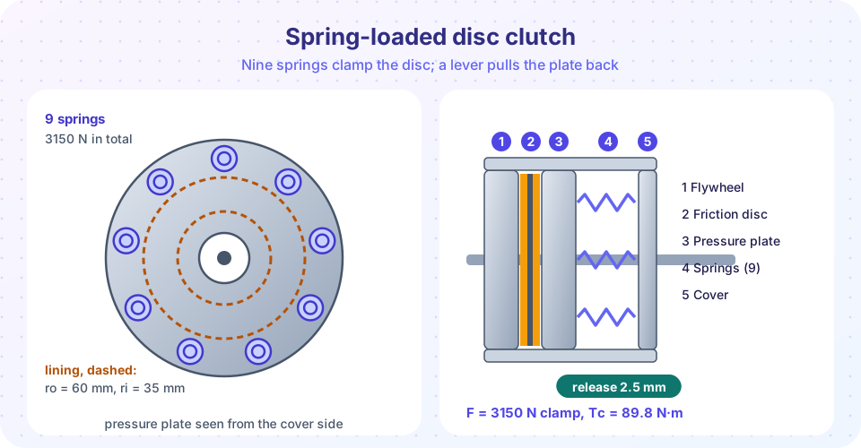
The third project joins two topics from chapters 6 and 7: a friction clutch and the springs that press it. The reducer of the first project is driven by a motor that cannot always be allowed to run into a loaded gearbox. A clutch between motor and reducer lets the motor start unloaded, protects the gears from shock and lets the line be stopped without switching the motor off. A single dry friction disc, clamped by a ring of coil springs and released by a lever, is the classic solution.
This project shows how a requirement flows through two kinds of calculation. The torque requirement fixes the friction disc and the clamp force. The clamp force then fixes the spring design, whose stress and travel are checked in the same way as in the springs lesson. At the end, a wear allowance tests whether the design still works when the lining is worn out.
What you will learn
- How to size a friction disc for a given motor torque, with a service factor and a pressure limit.
- How to estimate the engagement time and the heat of one engagement.
- How to design the clamping springs for the required total force and release stroke.
- How a wear allowance affects the clamp force and the torque capacity.
Key terms
- Torque capacity
Tc: the largest torque the clutch can transmit without slipping. - Design torque: the motor torque multiplied by a service factor.
- Release stroke: how far the pressure plate must move back to open the clutch.
- Wear allowance: the extra spring travel that is provided so that the lining can wear without losing too much clamp force.
Requirements and assumptions
The clutch sits on the motor shaft: 7.5 kW at 1450 rpm, so T = 9550 × 7.5 / 1450 = 49.4 N·m. We apply a service factor of 1.5 for frequent starts and light shock, which gives a design torque of 74.1 N·m.
| Assumption | Value |
|---|---|
Friction coefficient μ |
0.30 (dry organic lining on steel, assumed) |
| Allowable maximum lining pressure | 0.60 MPa (assumed) |
| Lining outer / inner radius | 60 mm / 35 mm (ratio 0.58, near the optimum 1/√3) |
Friction surfaces n |
2 (one disc with a lining on both sides) |
| Spring material | music wire, G = 81.7 GPa, Sut = 2211 / d^0.145 MPa, Ssy = 0.45 Sut |
| Number of springs | 9 on a circle |
| Release stroke | 2.5 mm |
Step 1: size the friction disc
Use the uniform wear model from the chapter on disc clutches. The maximum pressure acts at the inner radius, and the clamp force that is possible for the pressure limit is F = 2π pmax ri (ro − ri). The torque capacity for a given clamp force F is Tc = n μ F rm, with mean radius rm = (60 + 35)/2 = 47.5 mm.
- Force required for the design torque:
F = 74.1 / (2 × 0.30 × 0.0475) = 2600 N. The pressure at the inner radius would be2600 / (2π × 0.035 × 0.025) = 0.47 MPa. - We choose a clamp force of 3150 N, so as to leave a margin:
p_max = 0.573 MPa, below the limit of 0.60 MPa. - Torque capacity:
Tc = 2 × 0.30 × 3150 × 0.0475 = 89.8 N·m. The margin over the design torque is89.8 / 74.1 = 1.21.
Why not a lot more? A clutch with a very large margin does not slip when the load jams, and then the gearbox or the motor takes the overload. Slip is a feature of a clutch: it acts as a torque limiter at about 1.2 times the design torque.
Step 2: engagement and heat
Suppose the load that the clutch must accelerate, referred to the motor shaft, has an inertia I = 0.4 kg·m² and a steady load torque of 30 N·m. The motor speed is ω = 151.8 rad/s. The accelerating torque is Tc − TL = 89.8 − 30 = 59.8 N·m, so the slip time is t = I ω / (Tc − TL) = 0.4 × 151.8 / 59.8 = 1.02 s. The heat generated in the clutch is E = Tc ω t / 2 = 89.8 × 151.8 × 1.02 / 2 = 6.9 kJ. If the pressure plate and flywheel face together weigh 2.5 kg, the steel takes ΔT = 6.9 × 10³ / (2.5 × 500) = 5.5 K per engagement. At 30 starts an hour, the average heat is about 57 W, easily removed by the housing and air. The clutch will not overheat in this duty.
Step 3: the clamping springs
The clamp force is shared by nine springs: Fe = 3150 / 9 = 350 N each at the installed length. The release stroke of 2.5 mm compresses each spring further, so we need a spring that does not become too much stronger over 2.5 mm: we limit the rise to about 20 percent.
We choose music wire d = 3.5 mm, mean diameter D = 21 mm (index C = 6) and Na = 7 active coils with squared and ground ends (Nt = 9).
- Spring rate:
k = G d⁴ / (8 D³ Na) = 81,700 × 150.06 / (8 × 9261 × 7) = 23.6 N/mm. - Installed deflection:
y = 350 / 23.6 = 14.8 mm. - Force with the clutch released:
350 + 23.6 × 2.5 = 409 N, a rise of 17 percent. This is the maximum working load. - Stress at the release position:
Ks = 1 + 0.5/6 = 1.083,τ = 1.083 × 8 × 409 × 21 / (π × 3.5³) = 553 MPa. - Strength:
Sut = 2211 / 3.5^0.145 = 1844 MPa(about),Ssy = 0.45 Sut = 830 MPa, son = 830 / 553 = 1.50. - Lengths: solid length
Ls = 9 × 3.5 = 31.5 mm. Free lengthL0 = 31.5 + 1.15 × (14.8 + 2.5) = 51.4 mm. Installed length51.4 − 14.8 = 36.6 mm. When released,34.1 mm, which is still 2.6 mm above the solid length. - Buckling:
L0 / D = 2.45, below the guideline of 4. The springs also sit in seats on the plate.
The springs are not cycled fast (a clutch is engaged a few times an hour), so a fatigue and surge check is not critical. The release stroke happens at most a few hundred thousand times in the life of the clutch, so a modest fatigue check on the shear range from 350 to 409 N would be satisfactory.
Step 4: wear allowance
A lining wears: suppose each lining is allowed to lose 0.75 mm, so 1.5 mm of total thickness. The pressure plate moves forward, the springs extend by 1.5 mm and each loses 23.6 × 1.5 = 35 N. The clamp force falls to 9 × 314.6 = 2831 N and the torque capacity to 2 × 0.30 × 2831 × 0.0475 = 80.7 N·m, still above the design torque of 74.1 N·m. That is the reason for the generous original margin: the clutch has to work until the linings are worn out. A softer spring (lower k) would lose less clamp force with wear, and the lower rate is exactly why diaphragm springs, which have a very flat force curve, are used in cars.
The finished specification
| Item | Value |
|---|---|
| Friction lining | ro = 60 mm, ri = 35 mm, both sides of one disc, μ = 0.30 (assumed) |
| Clamp force | 3150 N new; 2830 N when worn by 1.5 mm |
| Torque capacity | 89.8 N·m new; 80.7 N·m worn; design torque 74.1 N·m |
| Springs | 9 × music wire, d = 3.5 mm, D = 21 mm, 7 active coils (9 total), squared and ground |
| Spring data | k = 23.6 N/mm, L0 = 51.4 mm, installed 36.6 mm, solid 31.5 mm |
| Stress | 553 MPa at release (n = 1.50 against shear yield) |
| Engagement | slip time about 1.0 s, heat about 6.9 kJ per start |
Common misconceptions
- "More clamp force is always better." The pressure limit of the lining, the heat and the release force all rise with clamp force, and a very strong clutch no longer protects the drive from overload.
- "A new clutch's torque is the torque it will have all its life." Wear reduces the spring force, so the design must work with the worn clutch.
- "A stiffer spring gives a more reliable clutch." A stiffer spring loses more force for the same wear, and it makes the release force larger.
- "The spring is checked only at the working length." The highest stress occurs at the release position, so check there, and check that the springs do not go solid.
Try it
The first TryIt does the whole calculation for the clutch and the springs. Change the number of springs, the wire diameter, the lining radii or the friction coefficient and watch the margins.
Press Run (or Ctrl + Enter) to see the result here.
Program input · what you'd type while the program runs
Type the answers before you press Run, one per line. Each time the program reads a line (with input()), it gets the next line from this box.
The second TryIt shows the force-deflection line of one spring with the installed point, the release point, the worn point and the solid point. It makes the wear allowance visible.
Press Run (or Ctrl + Enter) to see the result here.
Program input · what you'd type while the program runs
Type the answers before you press Run, one per line. Each time the program reads a line (with input()), it gets the next line from this box.
Check your understanding
Quick check · 5 questions
of 5 answered You scored / 5 · perfect!
-
1. A clutch has two friction surfaces, μ = 0.3, mean radius 50 mm and clamp force 2000 N. What is its torque capacity?
T = n μ F rm = 2 × 0.3 × 2000 × 0.050 = 60 N·m. -
2. Nine springs share a clamp force of 3150 N. What does each spring carry when installed?
3150 / 9 = 350 N. -
3. Why is the spring stress checked at the release position?
Releasing compresses the springs further, so the maximum force and stress occur at release. -
4. What is the main reason for a torque margin over the design torque when the clutch is new?
Wear reduces the clamp force. The margin keeps capacity above the design torque at the end of life. -
5. A spring has k = 20 N/mm. By how much does its force fall if the lining wears 1 mm?
ΔF = k Δx = 20 N/mm × 1 mm = 20 N.
Summary
- Size the disc from the design torque (motor torque times service factor), the friction coefficient, the mean radius and the pressure limit.
- Heat of one engagement
E = Tc ω t / 2; the plate temperature rise isE / (m c). - The clamping springs give
Fe = F / number of springsat the installed length and a slightly higher force at the release position, where the stress is checked. - A wear allowance shows how much torque capacity remains at the end of the lining life.
Track your progress
Create a free account to tick off lessons and pick up where you left off on any device.
of Machine Design lessons completed