


















Lesson 41 of 46 · Design Projects
Chapter 8 review: design projects
Review the three design projects: the gear reducer, its shafts and bearings, and the spring-loaded clutch, with a results table, a scaling study and ten mixed questions.
In this chapter you worked through three complete small designs. Each one started from a requirement and ended with a specification, and each one used the same working loop: write down numbers, choose, calculate, check every failure mode, adjust. This review puts the results side by side, so that you can see how one project feeds the next, and how the same habits made each of them work.
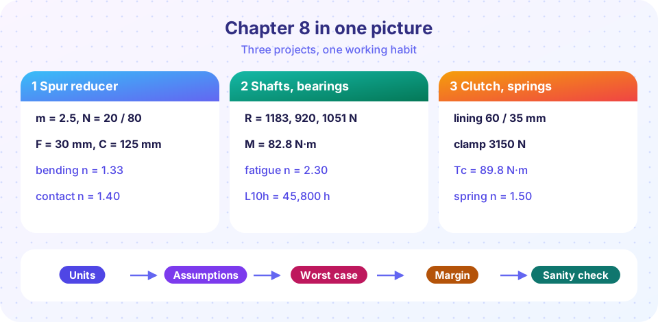
The three projects at a glance
| Project 1: reducer | Project 2: shafts and bearings | Project 3: clutch and springs | |
|---|---|---|---|
| Requirement | 7.5 kW, 1450 rpm, ratio 4, Ka = 1.25 |
Reactions, fatigue, 20,000 h | Motor torque 49.4 N·m, service factor 1.5 |
| Key choice | m = 2.5, N = 20/80, F = 30 mm |
Shafts 25 and 35 mm, bearings 25 mm medium and 35 mm light | Linings 60/35 mm, 9 springs, d = 3.5 mm |
| Main check | Bending n = 1.33, contact n = 1.40 |
Fatigue n = 2.30 and 4.79; bearing life 45,800 h and 380,000 h |
Torque margin 1.21 (80.7 N·m worn), spring n = 1.50 |
| Output | Wt = 1976 N, Wr = 719 N |
Reactions 1183, 920 and 1051 N | Clamp 3150 N, torque capacity 89.8 N·m |
| Lesson | Gear tooth strength, contact ratio | Shaft fatigue, L10 life | Friction torque, spring stress, wear |
Notice the flow of information: the gear project gave the tooth force that loaded the shaft and bearings in project 2, and the same motor torque set the clutch of project 3. In real machine design you will often go around the loop more than once, because a bearing that does not fit may force a change of the gear.
Habits to keep
- Write units on every line. A missing millimeter-to-meter conversion is the most common error in hand calculation.
- Record assumptions separately.
μ = 0.30,Kf = 1.8,Sut = 700 MPaand the allowable stresses were assumptions. If one changes, you know which results are affected. - Check the worst case, not the nominal one. The spring was checked at the released position; the clutch at worn-lining torque; the bearing with a shock factor.
- Match the margin to the uncertainty. A well-known load with good data allows 1.3. An uncertain load calls for 2 or more.
- Do a sanity check. Does a 7.5 kW motor produce 49 N·m at 1450 rpm? Is 3.8 m/s a sensible gear speed? If a number looks strange, find the reason before you continue.
How the designs would change
A good test of understanding is to change one requirement and predict the effect before you recalculate. Suppose the motor were 11 kW instead of 7.5 kW (about 72 N·m at 1450 rpm). The tangential tooth force rises by the ratio 11/7.5, the pinion would need a face width of roughly 43 mm instead of 30 mm (or a larger module), the bearing reactions rise by the same ratio and their L10 life falls by the cube, and the clutch clamp force and the spring load rise by 47 percent. Now suppose the required life doubles from 20,000 to 40,000 hours. The bearing rating needed rises by the cube root of 2, about 26 percent, while the gear and spring checks do not change at all. If you can make such predictions, you understand how the elements depend on each other.
Reading a design critically
When you review somebody else's design (or your own after a week), ask five questions. Are the requirements written with numbers? Are the assumptions listed? Has every failure mode of every element been checked, and at the worst case? Are the margins sensible for the uncertainty? Is there a record that a colleague could follow? A design that answers yes to all five is usually sound, whatever its details.
Try it
The first TryIt scales the reducer and the clutch from the projects to other motor powers. It finds the face width that the gears need (for the same module and tooth numbers) and the clutch clamp force. The pattern is instructive: the face width and the clamp force both rise in proportion to the torque, which is why larger drives are wider and not just taller.
Press Run (or Ctrl + Enter) to see the result here.
Program input · what you'd type while the program runs
Type the answers before you press Run, one per line. Each time the program reads a line (with input()), it gets the next line from this box.
The second TryIt is a proofreading exercise. A design record has been written with four mistakes in the way the numbers were used. Read each line, find the error and compare with the answers that the code prints.
Press Run (or Ctrl + Enter) to see the result here.
Program input · what you'd type while the program runs
Type the answers before you press Run, one per line. Each time the program reads a line (with input()), it gets the next line from this box.
Check your understanding
Quick check · 10 questions
of 10 answered You scored / 10 · perfect!
-
1. In the reducer project the pinion bending safety factor was 1.33. What did that number compare?
n = allowable / calculated = 220 / 166 = 1.33. -
2. A 22 kW drive at 1450 rpm replaces the 7.5 kW drive with the same gears. How does the needed face width change, approximately?
Tangential force is proportional to power, and the face width needed scales with force: 22/7.5 = 2.9. -
3. Why did the output shaft bearing have a life far beyond 20,000 h?
A 35 mm bore bearing is already strong, and the load at 362 rpm was small. -
4. Why did the clutch still work with 1.5 mm of lining wear?
The springs lose k × Δx per spring, which was small compared with 350 N. -
5. A design check gives n = 1.02 for bending. What should you do?
A margin of 2 percent does not allow for scatter in loads, material and manufacturing. -
6. Which step comes last in the design loop?
Document the choices, the assumptions and the checks, so that the design can be reviewed later. -
7. Spring force falls from 350 N to 315 N when the lining wears. What does this tell you about the spring rate (wear 1.5 mm)?
k = ΔF / Δx = 35 / 1.5 = 23 N/mm. -
8. Which loads act on the bearings of a spur gear shaft?
Spur gears have no axial force. The bearing reactions come from the tangential and radial tooth forces. -
9. What is the first thing to write down in a new project?
Requirements make every later check possible. -
10. What did the decision matrix of the overview lesson show?
Changing the weights changes the winner. The matrix makes your priorities explicit.
Summary
- The three projects used one loop: requirement, choice, calculation, check, iteration, record.
- Tooth force flows into shaft loads, bearing reactions and shaft stress; motor torque fixes the clutch.
- Check the worst case (release, wear, shock), match the margin to the uncertainty, and write down your assumptions.
Track your progress
Create a free account to tick off lessons and pick up where you left off on any device.
of Machine Design lessons completed