


















Lesson 18 of 46 · Shafts and Fasteners
Shaft Design for Bending, Torque and Fatigue
Design a rotating shaft step by step: reactions, shear and moment diagrams, stress concentration, the DE-Goodman diameter formula, a yield check and deflection limits, with a worked example.
Shafts are the backbone of almost every machine. They carry torque from a motor to a gear, a pulley or a wheel, and they are bent by the very forces that transmit that torque. Because a rotating shaft turns the bending stress into a fully reversed cycle, the first design check is fatigue, not static strength. In this lesson you will bring together everything from chapters 2 and 3 (loads, stress concentration, the Marin factors and the Goodman line) into a single method for sizing a shaft.
The method is a loop: find the loads, find the critical sections, pick a diameter, correct the endurance limit for that diameter, compute the stresses and check the factor of safety. For a first estimate there is a closed-form shortcut that you will derive and use.
What you will learn
- How shaft loads (bending, torque, axial) are found and combined.
- How to choose critical sections and apply stress concentration factors.
- How to use the DE-Goodman diameter formula for fatigue design.
- How to check yielding and deflection, and what design details matter.
Key terms
- Critical section: a location where the combination of stress and stress concentration is worst, usually under a gear or at a shoulder near a high moment.
- Shoulder (step): a change in diameter that locates a part against its seat; it must have a fillet.
- DE-Goodman: the fatigue criterion that uses the distortion-energy (von Mises) stresses with the Goodman line.
- Slope and deflection limits: bearings and gear teeth need the shaft to bend by no more than a small angle.
- Kf, Kfs: fatigue stress concentration factors for bending and torsion.
Loads on a shaft
Gears, pulleys, sprockets and couplings transmit torque T to the shaft and exert forces on it. For a spur gear the tooth force has a tangential part Ft = 2T/d and a radial part Fr = Ft tan φ. Together they make a force that is not parallel to a single plane, so the usual approach is to resolve the forces into two perpendicular planes, find the reactions and moment diagrams in each plane, and combine the moments as M = √(Mxy² + Mxz²).
In the typical shaft:
- Bending moment varies along the shaft and is fully reversed (each point on the surface passes from tension to compression once per turn).
- Torque is constant in steady running (a mean shear stress with zero alternating part) and only exists between the driving and the driven element.
- Axial load is usually small (helical gears and bearings may add some); we neglect it unless it is large.
A simple hand sketch showing where the torque enters and leaves, with the forces and bearing positions, shows which segment carries torque. Segments that do not carry torque only need to be checked for bending.
Worked example: the geometry
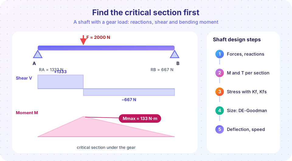
A 1045 cold-drawn steel shaft (Sut = 630 MPa, Sy = 530 MPa) is simply supported with bearings 300 mm apart. A spur gear with a pitch diameter of 100 mm sits 100 mm from the left bearing and transmits a tangential force Ft = 2,000 N, so the shaft carries a steady torque T = Ft × d/2 = 100 N·m through the gear. (To keep the example short we neglect the radial force, which in a real design adds a second plane.)
The reactions are RA = F b/L = 2,000 × 200/300 = 1,333 N and RB = 667 N. The maximum bending moment is under the gear: Mmax = F a b/L = 2,000 × 100 × 200/300 = 133.3 N·m. That is the critical section, and we assume a shoulder with a well-rounded fillet there, so Kf = 1.6 and Kfs = 1.4 (typical values; a full design would look them up from the radius).
The DE-Goodman diameter formula
At the critical section the stresses at the surface are, for a solid round shaft:
σa = 32 Kf Ma / (π d³)       (alternating bending)
τm = 16 Kfs Tm / (π d³)      (steady torsion)
with Ma = M, Tm = T. In von Mises terms σ′a = σa (no alternating torsion) and σ′m = √3 τm (no mean bending). Insert them in the Goodman line, 1/n = σ′a/Se + σ′m/Sut, and solve for d:
d = { (16 n / π) · [ 2 Kf Ma / Se + √3 Kfs Tm / Sut ] }^(1/3)
A subtle point: the endurance limit Se depends on d through the size factor kb, and d is what we are looking for. The procedure is therefore an iteration: guess d, compute kb and Se, evaluate the formula, update d, repeat. It converges in three or four steps.
For the example, n = 1.5, M = 133,333 N·mm, T = 100,000 N·mm, Se = ka kb ke Se′ with ka = 0.817 (machined), ke = 0.814 (99%), Se′ = 315 MPa. Starting at 25 mm, the loop converges to about d = 27.5 mm with Se ≈ 182 MPa. The next standard size up is 28 mm.
Press Run (or Ctrl + Enter) to see the result here.
Program input · what you'd type while the program runs
Type the answers before you press Run, one per line. Each time the program reads a line (with input()), it gets the next line from this box.
With 28 mm the fatigue factor is 1.58 and the yield factor about 4.6: fatigue governs by a wide margin, which is typical. A static-only design would have given a much smaller shaft that would fail in service.
Check yielding and deflection
Yield check. Compute the von Mises stress at the critical section from the maximum values, σ′max = √(σmax² + 3τmax²) (with stress concentration if the material is brittle, or without it for ductile material), and verify n = Sy/σ′max ≥ 1. It almost never governs, but overloads at start-up make it a necessary check.
Deflection and slope. A shaft that is strong enough may still bend too much. Excessive slope at bearings wears them out, because the inner ring tilts in the outer ring. Excessive deflection at gears misaligns the teeth, causing noise and edge contact. Typical limits are a few thousandths of a radian at ball bearings, a smaller slope at roller bearings and about 0.0005 rad at gear meshes. For a simply supported shaft with a point load, the deflection under the load is δ = F a² b² / (3 E I L) and the slope at the left support is θA = F b (L² − b²) / (6 E I L), where I = π d⁴/64.
Press Run (or Ctrl + Enter) to see the result here.
Program input · what you'd type while the program runs
Type the answers before you press Run, one per line. Each time the program reads a line (with input()), it gets the next line from this box.
The deflection is only a fraction of a millimeter, but the slope at the bearing is around 1.8 mrad for 28 mm, within the range acceptable for deep-groove ball bearings but too large for a precise roller bearing or for gears. A stiffer shaft (the slope falls with the fourth power of d) is then required. This is why stiffness, not strength, often fixes the final diameter in gearboxes.
Design details that matter
Most shaft failures come from details, not from the diameter.
- Fillets. Give every shoulder the largest radius the mating part allows. When a bearing needs a sharp corner, add an undercut or use a spacer ring.
- Keyways. The end of an end-milled keyseat has
Ktaround 2 to 3. Put keyseats away from the highest moment, or use a shrink fit or spline instead. - Retaining-ring grooves. Their
Ktcan be 3 to 5. Avoid them at critical sections. - Place loads near the bearings. A load close to a bearing produces a smaller moment and a smaller deflection.
- Short is stiff. Deflection grows with
L³. Keep the span as short as the layout allows. - Surfaces and fits. Ground surfaces raise
ka. Press fits cause fretting at the edge of the hub; blend the edge with a relief.
Common misconceptions
- "Size the shaft for the torque, because it is a power-transmission shaft." Bending usually dominates, and it is fully reversed. Torsion alone would give a much smaller diameter.
- "A stress of half the yield strength is safe." For a rotating shaft, 0.5 Sy may well exceed the endurance limit.
- "Once the diameter is fine, the shaft is done." Deflection, slope and critical speed are separate checks, and any of them can govern.
Check your understanding
Quick check · 5 questions
of 5 answered You scored / 5 · perfect!
-
1. Why is the bending stress on a rotating shaft treated as completely reversed?
A fixed bending moment places the tension side on one side of the shaft; the shaft rotates, so each fiber sees tension then compression. -
2. In the DE-Goodman formula, which stress term uses Se?
Se is paired with the alternating stress, Sut with the mean stress: d³ ∝ 2 Kf Ma / Se + √3 Kfs Tm / Sut. -
3. Why is the diameter calculation iterative?
kb = 1.24 d^−0.107 so the endurance limit shrinks as d grows. -
4. Under a point load F at distance a from A on a shaft of length L (b = L − a), the reaction at A is
Moments about B give RA × L = F × b, so RA = F b / L. -
5. Which change reduces both the stress concentration and the fatigue risk at a shoulder?
A large radius lowers Kt and Kf.
Summary
- Shaft bending is fully reversed and torque is steady: fatigue governs.
- Find reactions, shear and moment diagrams, choose critical sections and use
Kf,Kfs. d = {(16n/π)[2 Kf Ma/Se + √3 Kfs Tm/Sut]}^(1/3), iterating becauseSedepends ond; round up.- Check yield, then deflection and slope; details such as fillets and keyways dominate real failures.
Track your progress
Create a free account to tick off lessons and pick up where you left off on any device.
of Machine Design lessons completed