


















Lesson 39 of 46 · Design Projects
Project: shafts and bearings for the reducer
Continue the reducer project: find bearing reactions and bending moments from the gear forces, check the shaft for fatigue, and select deep groove bearings for 20,000 hours.
The gear pair of the previous project is only the middle of the gearbox. The gears sit on shafts, and the shafts turn in bearings. The force that the teeth exchange, Wt = 1976 N and Wr = 719 N, does not disappear: it passes into the shaft, bends it, and becomes the load on the two bearings. This project follows that force from the tooth to the housing.
The route is a standard one. First draw the shaft as a beam and find the reactions by statics. Then find the bending moment at the gear and check the shaft for fatigue, with the torque and the stress concentration of the keyway or shoulder. Finally, convert the reactions into equivalent bearing loads and select bearings for the required life.
What you will learn
- How to turn the tooth force into bearing reactions and bending moments for a two-bearing shaft.
- How to check a shaft for combined bending and torsion in fatigue.
- How to select deep groove ball bearings from required life and shaft diameter.
- How the shaft diameter, not the life, may set the bearing size.
Key terms
- Reaction
R: the force that a bearing exerts on the shaft to hold it in equilibrium. - Resultant: the combined (vector sum) of the tangential and radial components.
- Stress concentration factor
Kf: the multiplier on stress caused by a keyway, shoulder or groove. - Equivalent load
P: the radial load used in the L10 formula, including a factor for shock.
The layout
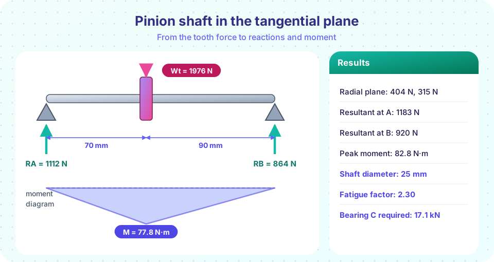
The pinion shaft is supported by bearings A and B that are 160 mm apart. The pinion sits 70 mm from A (so 90 mm from B). The output shaft has the gear in the middle: 80 mm from each bearing. The gears are spur gears, so there is no axial force; the bearings take radial load only. The shaft transmits the full torque, T1 = 49.4 N·m on the pinion shaft and T2 = 194 N·m on the output shaft. The tooth forces are Wt = 1976 N and Wr = 719 N.
Step 1: reactions
The two force components act in perpendicular planes, so find the reactions in each plane, then combine. For a point load W at a distance a from A on a span L, with b = L − a:
R_A = W b / L R_B = W a / L
Pinion shaft (L = 160, a = 70, b = 90):
- Tangential plane:
R_At = 1976 × 90 / 160 = 1112 N,R_Bt = 1976 × 70 / 160 = 864 N. - Radial plane:
R_Ar = 719 × 90 / 160 = 404 N,R_Br = 719 × 70 / 160 = 315 N. - Resultants:
R_A = √(1112² + 404²) = 1183 N,R_B = √(864² + 315²) = 920 N.
Output shaft (gear in the middle): each plane splits equally, R = ½ √(1976² + 719²) = 1051 N at both bearings.
Step 2: bending moment and shaft stress
The bending moment is largest under the gear. For the pinion shaft, M = R_A × a in each plane: M_t = 1112 × 0.070 = 77.8 N·m and M_r = 404 × 0.070 = 28.3 N·m, so the resultant is M = √(77.8² + 28.3²) = 82.8 N·m. For the output shaft, M = 1051 × 0.080 = 84.1 N·m.
For a solid shaft of diameter d, the bending stress at the surface is σ = 32 M / (π d³) and the torsional shear stress is τ = 16 T / (π d³).
Pinion shaft with d = 25 mm: σ = 32 × 82.8 / (π × 0.025³) = 54.0 MPa, τ = 16 × 49.4 / (π × 0.025³) = 16.1 MPa. The combined von Mises stress √(σ² + 3τ²) is 60.8 MPa, much less than the yield strength of any shaft steel. That is a static check only. Because the shaft turns, every point on its surface goes through a full cycle of tension and compression in each revolution, and fatigue is the real limit.
Step 3: fatigue check
Use a steel with Sut = 700 MPa (assumed). The rotating-beam endurance limit of a polished specimen is 0.5 Sut = 350 MPa. Correct it for the machined surface (factor 0.8) and for size: kb = 1.24 d^(−0.107) = 0.879 at d = 25 mm. So Se = 350 × 0.8 × 0.879 = 246 MPa. The keyway or a shoulder fillet has an assumed Kf = 1.8.
The bending stress is fully reversed: σa = Kf σ = 1.8 × 54.0 = 97 MPa. The torque is steady, so it contributes a mean stress, which in the von Mises sense is σm = √3 τ = 27.9 MPa. The Goodman criterion gives
1/n = σa / Se + σm / Sut = 97/246 + 27.9/700 = 0.434 + 0.040 → n = 2.30
The same calculation for the output shaft with d = 35 mm (σ = 20.0 MPa, τ = 23.0 MPa, Se = 237 MPa) gives n = 4.79. Both are comfortably above a typical target of 1.5 to 2. This is the same fatigue idea that you met in the earlier chapter on fatigue and failure; here it is applied to a real shaft.
Step 4: bearing selection
Each bearing sees a radial load only, so P = Fr times a shock factor of 1.2 (assumed, for light shock). The required life is 20,000 h.
| Bearing | Speed | Reaction | P (×1.2) |
L10 needed |
C required |
|---|---|---|---|---|---|
| Pinion shaft A | 1450 rpm | 1183 N | 1.42 kN | 1740 M rev | 1.42 × 1740^(1/3) = 17.1 kN |
| Pinion shaft B | 1450 rpm | 920 N | 1.10 kN | 1740 M rev | 13.3 kN |
| Output shaft A and B | 362.5 rpm | 1051 N | 1.26 kN | 435 M rev | 9.6 kN |
Use a small illustrative catalog of deep groove ball bearings (bore, series, C): 25 mm light 14.0 kN, 25 mm medium 22.5 kN, 35 mm light 25.5 kN. The pinion shaft has a 25 mm seat. A light bearing (C = 14.0 kN) would give only (14.0/1.42)³ × 10⁶ / (60 × 1450) = 11,000 h at bearing A, which fails. The 25 mm medium series (C = 22.5 kN) gives 45,800 h at A and 97,300 h at B. Bearing B alone could be a light one (about 23,400 h), and the TryIt below picks that, but using the same medium size at both ends is simpler and keeps one spare part number.
On the output shaft the 35 mm light bearing (C = 25.5 kN) lasts (25.5/1.26)³ × 10⁶ / (60 × 362.5) = 380,000 h. That is a lot more than needed. The bearing is large because the shaft diameter was set by torque and by the need for a keyway and a stiff coupling, not by the bearing life. Oversized life is common on slow shafts.
Step 5: what to write down
The record for the shafts and bearings: shaft diameters 25 mm and 35 mm; tooth force and reaction table; stress and fatigue factors with assumptions (Sut, Kf, surface and size factors); bearing designations with C, P and computed life; shock factor. And a note of what is not yet covered: shaft deflection and slope at the gears (they must be small, so that the teeth contact evenly along the face), critical speed, the fits of bearings and seals, and the keyways.
Common misconceptions
- "Half of the tooth force goes to each bearing." Only if the gear is in the middle. The nearer bearing carries more.
- "If the stress is far below yield, the shaft is safe." A rotating shaft fails by fatigue at stresses well below yield, especially at keyways and shoulders.
- "Longest life is best for the bearing." A bearing life of 380,000 h on a machine that will be scrapped in 20 years is no virtue. The right bearing life is the one that matches the machine life, with the lowest cost.
- "The radial force can be ignored." It adds in vector sum to the tangential force. Here it increases the reaction at A from 1112 N to 1183 N.
Try it
The first TryIt does the whole calculation for both shafts: reactions, bending, fatigue and the bearing choice from the small catalog.
Press Run (or Ctrl + Enter) to see the result here.
Program input · what you'd type while the program runs
Type the answers before you press Run, one per line. Each time the program reads a line (with input()), it gets the next line from this box.
The second TryIt draws the shear force and bending moment diagrams of the pinion shaft in the tangential and radial planes, and the resultant moment.
Press Run (or Ctrl + Enter) to see the result here.
Program input · what you'd type while the program runs
Type the answers before you press Run, one per line. Each time the program reads a line (with input()), it gets the next line from this box.
Check your understanding
Quick check · 5 questions
of 5 answered You scored / 5 · perfect!
-
1. A gear force of 2000 N acts 60 mm from bearing A on a 200 mm span. What is the reaction at A?
R_A = W b / L = 2000 × 140 / 200 = 1400 N. The nearer bearing (A) carries more. -
2. Wt = 1000 N and Wr = 364 N act at the same point. What is the magnitude of the resultant force?
The components are perpendicular: √(1000² + 364²) = 1064 N (that is Wt / cos 20°). -
3. Why is fatigue the main check for a rotating shaft carrying a gear?
A rotating shaft under constant bending load makes each surface point cycle between tension and compression. -
4. A bearing needs L10 = 800 million revolutions at P = 2 kN. What C is required for a ball bearing?
C = P L10^(1/3) = 2 × 800^(1/3) = 2 × 9.28 = 18.6 kN. -
5. Why is the life of the output shaft bearing so much larger than required?
The bearing bore must match the shaft; the smallest bearing for a 35 mm bore is already strong for this load.
Summary
- Tooth forces become shaft loads: find the reactions in two planes, then combine them as a vector sum.
- The moment peaks under the gear; check the shaft for fatigue with
Kf,Seand the Goodman line. - Bearings:
P = shock factor × reaction,C = P L10^(1/3); choose a catalog size that meets the life and the shaft bore. - Record assumptions and list what is still to be checked: deflection, critical speed, fits and seals.
Track your progress
Create a free account to tick off lessons and pick up where you left off on any device.
of Machine Design lessons completed