


















Lesson 43 of 46 · Projects and Practice
Capstone: a complete conveyor drive
Put it all together: design a motor, V-belt, spur reducer, drum shaft bearings and emergency band brake for a belt conveyor, with every step calculated and checked.
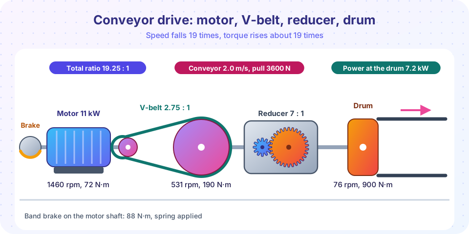
This is the capstone of the course: one machine, many elements. A belt conveyor moves material at a steady speed. Its drive has to take power from an electric motor, reduce the speed from 1460 rpm to about 76 rpm, and turn the conveyor's drum. It must stop the belt safely in an emergency. The chain of elements is a V-belt drive, a spur gear reducer, the drum shaft with its bearings, and a band brake on the motor shaft.
The goal is not new theory but practice at joining what you have learned. Each step uses one of the earlier lessons, and each result feeds into the next. When you can follow the numbers from the conveyor belt back to the motor, you can design most drives.
What you will learn
- How to turn a conveyor requirement (belt speed, pull) into drum speed, torque and power.
- How to split a total speed ratio between a belt stage and a gear stage.
- How to check the belt, the gears, the drum bearings and an emergency brake in one calculation.
- How to present all results in a single design table.
Key terms
- Belt pull: the net force the drum must exert on the conveyor belt.
- Overall efficiency: the product of the efficiencies of belt, gears and bearings.
- Emergency stop: braking the loaded conveyor to rest within a stated time.
- Equivalent inertia: the single inertia on the brake shaft that has the same kinetic energy as the whole moving system.
Requirement
| Item | Value |
|---|---|
| Belt speed | 2.0 m/s |
| Drum diameter | 0.50 m |
| Net belt pull | 3600 N |
| Duty | 16 hours per day, moderate shock |
| Moving mass (belt, load, rollers, referred to the belt) | 2500 kg |
| Motor | 4-pole, 1460 rpm, standard size to be chosen |
| Emergency stop | within 2 s from full speed |
| Required bearing life (drum shaft) | 40,000 h |
Step 1: drum speed, power and torque
Drum speed: n = v / (π D) × 60 = 2.0 / (π × 0.5) × 60 = 76.4 rpm. Power at the drum: P = F v = 3600 × 2.0 = 7.2 kW. Torque at the drum: T = F D / 2 = 3600 × 0.25 = 900 N·m.
Step 2: efficiency and motor
Typical values (assumed): V-belt 0.96, spur gear pair 0.98, two pairs of bearings 0.99 each, so the overall efficiency is 0.96 × 0.98 × 0.99² = 0.92. The motor must deliver 7.2 / 0.92 = 7.8 kW. The nearest standard size above that is 11 kW, which also covers the moderate-shock service factor (about 1.4). We design the belt and the gears for the motor rating, 11 kW, which is the usual and conservative choice.
Step 3: split the speed ratio
The total ratio is 1460 / 76.4 = 19.1. A belt drive is good at the first, high-speed stage (it absorbs shock and costs little), while a gear pair is better at the low-speed stage, where torque is high and a belt would be huge. Choose a V-belt ratio of 2.75 and a spur ratio of 7, so the total is 19.25 and the drum turns at 1460 / 19.25 = 75.8 rpm, giving a belt speed of 1.99 m/s, within 1 percent of the requirement.
Step 4: V-belt stage
Pulleys d = 140 mm and D = 385 mm (ratio 2.75), center distance C = 500 mm, three V-belts with a groove half-angle of 18°, μ = 0.3 and a total mass per meter of m′ = 0.45 kg/m.
- Belt speed:
v = π × 0.140 × 1460 / 60 = 10.7 m/s. - Wrap on the small pulley:
sin α = 245/1000,θ = π − 2α = 2.647 rad = 151.6°. - Belt length:
L = 2 × 500 + π × 525/2 + 245²/2000 = 1855 mm. - Effective friction:
μ′ = 0.3 / sin 18° = 0.971;e^(μ′θ) = e^2.57 = 13.1. - Net pull
F1 − F2 = 11,000 / 10.7 = 1028 NandFc = 0.45 × 10.7² = 51.5 N. F2 = 1028 / (13.1 − 1) + 51.5 = 137 NandF1 = 1165 N. Total belt tension on the shafts: about1301 N. Per belt:F1 ≈ 388 N, checked against the manufacturer's rating.
Step 5: spur gear reducer
The reducer input is 1460 / 2.75 = 531 rpm. Torque at the input, taking 11 kW × 0.96 = 10.56 kW: T = 9550 × 10.56 / 531 = 190 N·m.
Choose module m = 4 mm, N1 = 20, N2 = 140, face width F = 48 mm (12 m), Ka = 1.25.
d1 = 80 mm,d2 = 560 mm,C = 320 mm; pitch-line speedv = 2.22 m/s,Kv = 1.37.Wt = 2 × 190 / 0.080 = 4749 N,Wr = 1728 N.- Bending (pinion):
σ = 1.25 × 1.365 × 4749 / (48 × 4 × 0.322) = 131 MPa; with the 220 MPa allowable,n = 1.68. - Contact:
σH = 629 MPa, with 950 MPa allowable,n = 1.51. Contact ratio 1.72. - Output torque:
T = 190 × 7 × 0.98 = 1303 N·m, the maximum that the drum shaft would see at the full motor rating. The normal running torque is 900 N·m.
Step 6: drum shaft bearings
The drum shaft carries the belt tensions and the gear force. Suppose the statics of the drum shaft give a resultant reaction of R = 7.0 kN on the most loaded bearing (an assumed value for this exercise; in a real design it comes from a free body diagram like the one in project 2). With a shock factor of 1.2, P = 8.4 kN. At 76 rpm for 40,000 h, L10 = 40,000 × 60 × 76 / 10⁶ = 182 million revolutions. Required rating: ball bearing, C = 8.4 × 182^(1/3) = 47.6 kN; roller bearing (p = 10/3), C = 8.4 × 182^0.3 = 40.0 kN. A heavy-series ball bearing or a spherical roller bearing on a 70 to 80 mm shaft would satisfy this.
Step 7: the emergency band brake
Place the brake on the motor shaft, where the torque is lowest. The kinetic energy at full speed is the linear energy ½ × 2500 × 1.98² = 4.9 kJ plus the rotor and pulley, I = 0.35 kg·m² at ω = 152.9 rad/s, ½ I ω² = 4.1 kJ: E = 9.0 kJ. The equivalent inertia is I_eq = 2E / ω² = 0.77 kg·m². To stop in 2 s, T = I_eq ω / t = 59 N·m. With a design factor of 1.5, T = 88 N·m. We neglect the help of the conveyor's own friction, which is conservative.
A band brake on a 0.20 m diameter drum (r = 0.10 m, band width 40 mm, wrap 270°, μ = 0.3):
F1 − F2 = 88 / 0.10 = 882 N;F1/F2 = e^(0.3 × 4.712) = 4.11.F2 = 284 N,F1 = 1166 N; pressurep_max = 1166 / (0.04 × 0.10) = 0.29 MPa.- With a lever
a = 400 mm,b = 80 mmand the slack end on the lever:Fa = 284 × 80 / 400 = 57 N. This is a light spring-and-solenoid force, so the brake can be a spring-applied, electrically released, fail-safe unit. - Heat: if the drum has a mass of 8 kg,
ΔT = 9000 / (8 × 460) = 2.4 K. No problem.
The design table
| Element | Key data | Checks |
|---|---|---|
| Motor | 11 kW, 1460 rpm | 7.8 kW needed, T = 72 N·m rated |
| V-belt | 3 belts, d = 140, D = 385, C = 500 mm |
F1 = 1165 N, shaft load 1301 N |
| Reducer | m = 4, 20/140, F = 48, C = 320 mm |
bending 1.68, contact 1.51, CR = 1.72 |
| Drum shaft bearings | C ≥ 40 to 48 kN |
40,000 h |
| Brake | band, r = 0.1 m, 270°, 88 N·m |
p_max = 0.29 MPa, Fa = 57 N |
Common misconceptions
- "Design the drive for the load power." Drive elements are sized for the motor rating (and service factor), because the motor can deliver that power if the load jams.
- "Put the brake on the slow shaft because that is where the load is." The torque is much lower on the fast shaft; a smaller brake is enough. Keep in mind that a brake on the motor shaft acts through the gears and belt, so a broken belt would leave the load free.
- "One stage should do the whole ratio." A single stage of 19:1 would require a huge gear. Splitting the ratio is cheaper and smaller.
- "Efficiency can be ignored." Here the losses are 8 percent of the motor power, about 0.6 kW, which ends up as heat.
Try it
The first TryIt runs the complete chain of calculations. Change the belt pull, the speed or the motor size and follow the changes down the chain.
Press Run (or Ctrl + Enter) to see the result here.
Program input · what you'd type while the program runs
Type the answers before you press Run, one per line. Each time the program reads a line (with input()), it gets the next line from this box.
The second TryIt draws the power flow through the drive, from the motor shaft to the drum, with the loss at each element.
Press Run (or Ctrl + Enter) to see the result here.
Program input · what you'd type while the program runs
Type the answers before you press Run, one per line. Each time the program reads a line (with input()), it gets the next line from this box.
Check your understanding
Quick check · 5 questions
of 5 answered You scored / 5 · perfect!
-
1. A conveyor belt moves at 1.5 m/s over a drum of 0.4 m diameter. What is the drum speed?
n = v / (π D) × 60 = 1.5 / (π × 0.4) × 60 = 71.6 rpm. -
2. Why is the brake placed on the motor shaft?
Speed is highest and torque lowest on the motor shaft, so the same energy is absorbed with less torque. -
3. Why is the drive designed for the motor rating instead of the load power?
Drive elements must survive what the motor can deliver, not only the normal load. -
4. The V-belt stage ratio is 2.75 and the gear ratio is 7. What is the total ratio?
Ratios of stages in series multiply: 2.75 × 7 = 19.25. -
5. The energy to be absorbed in an emergency stop is 9 kJ in 2 s from 152.9 rad/s. What is the average braking power?
P = E / t = 9000 / 2 = 4500 W.
Summary
- Start at the conveyor: speed, pull, drum speed, power and torque; correct for efficiency and choose a standard motor.
- Split the ratio: a V-belt for the fast stage (2.75) and a spur reducer for the slow stage (7).
- Check the belt (tensions, shaft load), the gears (bending 1.68, contact 1.51), the drum bearings (
C ≥ 40 to 48 kN) and the brake (88 N·m, lever force 57 N). - Design elements for the motor rating, put the brake on the high-speed shaft and record the whole chain in one table.
Next: Glossary
Track your progress
Create a free account to tick off lessons and pick up where you left off on any device.
of Machine Design lessons completed