


















Lesson 38 of 46 · Design Projects
Project: a spur gear reducer
Design a single-stage spur gear reducer step by step: requirements, tooth counts and module search, bending and contact checks, safety factors and a final specification.
A single-stage spur gear reducer is the classic first design project. It is small enough to finish in an afternoon, and it uses almost everything from the gears chapter: geometry, force, bending and contact stress, contact ratio, speed and lubrication. The assignment is a typical industrial one: a motor drives a conveyor through a gearbox, and your job is to choose the gears.
We will work through the project exactly the way you would on a real job. First write the requirements and the assumptions. Then search for a good set of tooth counts, module and face width, check every failure mode, and finally write down the specification. Wherever a number is assumed instead of measured, we say so.
What you will learn
- How to turn a requirement into a design search over standard modules and tooth counts.
- How to check bending, contact, contact ratio and speed, and read the safety factors.
- How a change of one parameter shows up in all the checks.
- How to write the specification that goes to the shop.
Key terms
- Service factor
Ka: a multiplier for the real load, for example 1.25 for light shock. - Face width
F: the axial length of the teeth in contact, here chosen as 12 times the module. - Safety factor
n: allowable stress divided by the calculated stress. - Design search: trying all standard combinations and keeping the ones that pass.
Requirements and assumptions
| Item | Value |
|---|---|
| Motor power | 7.5 kW |
| Input speed | 1450 rpm |
| Required ratio | 4 (target output about 360 rpm) |
| Duty | 8 hours per day, light shock |
| Life | 20,000 hours |
Service factor Ka |
1.25 |
| Gear material | through-hardened alloy steel (assumed) |
| Allowable bending stress | 220 MPa (assumed from material data) |
| Allowable contact stress | 950 MPa (assumed from material data) |
| Pressure angle | 20° |
| Required safety factors | bending 1.3 or more, contact 1.2 or more, contact ratio 1.4 or more |
The assumed stress limits are placeholders for the exercise. In a real design they come from the standard (ISO 6336 or AGMA 2001) and the steel and heat treatment you specify.
Step 1: the load
The motor torque is T1 = 9550 × 7.5 / 1450 = 49.4 N·m. With the design load factor, the gears must be checked at Ka T1. Once a pinion diameter is chosen, the tangential force follows from Wt = 2 T1 / d1.
Step 2: search the design space
You have three free choices: the module m, the pinion tooth count N1 (so N2 = 4 N1) and the face width F. Keep the tooth count of the pinion at 18 or more to avoid undercutting, use standard modules (2, 2.5, 3, 4 mm) and keep F between 8 and 12 modules. For every combination, compute the pinion bending stress, the contact stress and the contact ratio, and keep those which pass. Then choose the most compact: the smallest center distance. A smaller gearbox is cheaper and lighter.
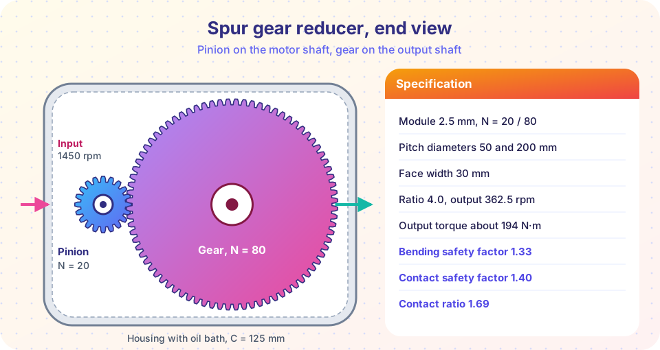
The search is easy to do by computer. The TryIt below runs it with Ka = 1.25. Among the combinations that satisfy the limits, the smallest center distance is C = 125 mm with m = 2.5 mm, N1 = 20, N2 = 80 and F = 30 mm.
Step 3: check the selected design
Geometry. d1 = 2.5 × 20 = 50 mm, d2 = 200 mm, C = 125 mm. Tip diameters 55 mm and 205 mm; root diameters 43.75 mm and 193.75 mm. Face width F = 30 mm = 12 m.
Speed. v = π × 0.050 × 1450 / 60 = 3.80 m/s. At this speed splash lubrication in an oil sump is entirely adequate. Velocity factor Kv = (6.1 + 3.80) / 6.1 = 1.62.
Forces. Wt = 2 × 49.4 / 0.050 = 1976 N, Wr = Wt tan 20° = 719 N, W = 2103 N.
Bending (Lewis). Pinion: σ = Ka Kv Wt / (F m Y) = 1.25 × 1.62 × 1976 / (30 × 2.5 × 0.322) = 166 MPa, so n = 220/166 = 1.33. Gear (Y = 0.435 for 80 teeth): σ = 123 MPa, n = 1.79. The pinion governs.
Contact (Hertz). ρ1 = 8.55 mm, ρ2 = 34.2 mm. σH = 189.8 √[1.25 × 1976 / (30 × cos 20°) × (1/8.55 + 1/34.2)] = 679 MPa, n = 950/679 = 1.40.
Contact ratio. CR = 1.69, comfortably above 1.4.
Output. Speed 1450 / 4 = 362.5 rpm. Output torque: T2 = 49.4 × 4 × 0.98 = 194 N·m with a mesh efficiency of 98 percent (typical for a well-lubricated spur pair, assumed here). Output power 7.5 × 0.98 = 7.35 kW; the lost 150 W heats the oil and housing.
All checks pass with a margin, so the design is accepted.
Step 4: iterate and explore
A design is not understood until you see how it reacts to changes. Narrow the face from 30 to 24 mm and the pinion bending stress rises to 207 MPa, n = 1.06: it fails the 1.3 requirement. Raise the module from 2.5 to 3 mm at the same face width of 30 mm and the stress falls, but the center distance goes up to 150 mm. A wider face costs gear blank width, and the housing has to be wider. These trade-offs are the substance of design. The second TryIt shows them as curves.
Step 5: the specification
| Item | Specification |
|---|---|
| Gear type | Spur, full depth, 20° pressure angle |
| Module | 2.5 mm |
| Teeth | Pinion 20, gear 80 |
| Pitch diameters | 50 mm and 200 mm |
| Center distance | 125 mm |
| Face width | 30 mm |
| Material | Through-hardened alloy steel (assumed) |
| Speed ratio | 4.0, output 362.5 rpm |
| Output torque | about 194 N·m at 7.5 kW input |
| Lubrication | Oil bath (splash), pitch-line speed 3.8 m/s |
| Loads on the shafts | Wt = 1976 N, Wr = 719 N (input and output shafts, equal and opposite) |
The shaft loads are the starting point of the next project.
Common misconceptions
- "The smallest gear that passes is the best." Compact is good, but a design with a margin of only 1.02 leaves no allowance for load uncertainty, wear or temperature.
- "Any combination of m and N that gives the right pitch diameter is equivalent." A larger module with fewer teeth has a stronger tooth but a lower contact ratio and more noise.
- "If bending passes, contact passes too." They are independent checks. Often contact governs a hardened gear.
- "The service factor is a safety factor." It adjusts the load for operating conditions (shock). The safety factor is applied on top of it.
Try it
The first TryIt runs the design search and prints the full check of the chosen design. Change Ka, the allowable stresses or the required safety factors and see how the choice changes.
Press Run (or Ctrl + Enter) to see the result here.
Program input · what you'd type while the program runs
Type the answers before you press Run, one per line. Each time the program reads a line (with input()), it gets the next line from this box.
The second TryIt plots the bending and contact safety factors against the face width for three modules (with N1 = 20). It shows which combinations pass and how much face width is needed.
Press Run (or Ctrl + Enter) to see the result here.
Program input · what you'd type while the program runs
Type the answers before you press Run, one per line. Each time the program reads a line (with input()), it gets the next line from this box.
Check your understanding
Quick check · 5 questions
of 5 answered You scored / 5 · perfect!
-
1. What is the motor torque for 7.5 kW at 1450 rpm?
T = 9550 × 7.5 / 1450 = 49.4 N·m. -
2. A design check gives 220 MPa allowable and 166 MPa calculated bending stress. What is the safety factor?
n = 220 / 166 = 1.33. -
3. Why does the pinion usually govern the bending check?
Both gears carry the same force, but the pinion has fewer teeth and thus a smaller Y, giving higher stress. -
4. What is the effect of narrowing the face width from 30 mm to 24 mm?
σ is inversely proportional to F: 30/24 = 1.25. -
5. Which item is NOT part of the specification you hand to the shop?
The specification gives dimensions, material, tolerances and lubrication. The safety factor belongs in the design record.
Summary
- Start from the torque
T = 9550 P / nand the service factor; search standard modules, tooth counts and face widths. - Check bending, contact, contact ratio, speed and lubrication; read the safety factors.
- The chosen design:
m = 2.5 mm,N = 20/80,F = 30 mm,C = 125 mm,n_bending = 1.33,n_contact = 1.40. - Document the spec and carry the loads
Wt = 1976 N,Wr = 719 Nto the shaft design.
Track your progress
Create a free account to tick off lessons and pick up where you left off on any device.
of Machine Design lessons completed