


















Lesson 25 of 46 · Gears
Helical, bevel and worm gears
Compare helical, bevel and worm gears: thrust forces, cone angles, lead angle, self-locking and efficiency, with worked force calculations.
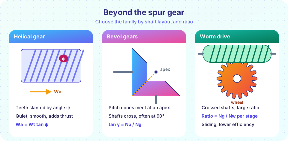
Spur gears are simple, cheap and efficient, but they have limits. They are noisy at high speed, they need parallel shafts, and their ratio per stage is limited to about 6 to 8. The other three gear families remove one limit each. Helical gears run quietly and carry more load, bevel gears turn the power through an angle, and worm gears give a very large ratio in one compact stage, with the bonus that some of them cannot be driven backwards.
Each family adds a new force or a new angle to the picture from the previous lesson. You do not need new principles: you resolve the tooth force into components, exactly as you did for the spur gear, but now in three dimensions.
What you will learn
- Explain how the helix angle changes the geometry and creates an axial thrust.
- Calculate the three force components in a helical and a bevel pair.
- Compute the lead angle, ratio and efficiency of a worm drive, and decide when it self-locks.
- Choose the right gear family for a given shaft layout and ratio.
Key terms
- Helix angle
ψ: the angle between the tooth direction and the gear axis. - Normal module
mn: the module measured perpendicular to the tooth. The transverse module ismt = mn / cos ψ. - Pitch cone angle
γ: half the apex angle of a bevel gear's pitch cone. - Lead
L: the axial distance a worm advances in one turn. The lead angleλsatisfiestan λ = L / (π dw). - Self-locking: a drive that cannot be turned by the output side, only by the input.
Helical gears
A helical gear is a spur gear whose teeth are cut at an angle ψ, typically 15° to 30°, to the axis. Think of a stack of thin spur gears, each rotated slightly from the one below. The teeth then engage gradually along their length instead of all at once, so the load rises and falls smoothly. The contact ratio goes up (the total includes an extra face contact ratio from the slant), and so do the load capacity and the quietness. That is why car transmissions, whose gears must be quiet, use helical teeth.
Two gears can mesh only if they have equal helix angles of opposite hand (one left-hand, one right-hand) for parallel shafts. Geometry follows the transverse plane, the plane perpendicular to the axis:
mt = mn / cos ψ d = mt N = mn N / cos ψ
Standard cutters are specified in the normal plane, so mn takes the standard values (2, 2.5, 3, ...) and the pitch diameter is slightly larger than for a spur gear of the same teeth. The center distance becomes C = mn (N1 + N2) / (2 cos ψ), which can be adjusted by choosing ψ; that is a design freedom spur gears do not have.
Forces in a helical gear
The slant brings a third force. For the transmitted torque T:
Wt = 2T / d
Wr = Wt tan φn / cos ψ
Wa = Wt tan ψ
where φn is the normal pressure angle, usually 20°. The axial force Wa pushes the gear along its shaft and must be taken by a bearing that can carry thrust (an angular-contact ball bearing or a tapered roller bearing; see the bearings chapter). It grows with the helix angle: at ψ = 30°, Wa = 0.58 Wt. To cancel it, double-helical ("herringbone") gears use two opposite helices side by side, and the two thrusts cancel inside the gear.
Worked example: helical pair
A pinion has N = 24, mn = 3 mm, ψ = 20° and transmits T = 100 N·m.
- Transverse module:
mt = 3 / cos 20° = 3.192 mm; pitch diameterd = 3.192 × 24 = 76.6 mm. Wt = 2 × 100 / 0.0766 = 2610 N.Wr = 2610 × tan 20° / cos 20° = 1011 N.Wa = 2610 × tan 20° = 950 N.
Compare a spur gear of the same torque and diameter: the radial force would be 2610 × 0.364 = 950 N. The helical radial force is a bit larger, and there is a new axial force of the same size.
Bevel gears
When the shafts meet at an angle, usually 90°, the pitch surfaces are not cylinders but cones that share an apex. Straight bevel gears have teeth that point at the apex. Spiral bevel gears curve their teeth for a smoother mesh, like helical gears do. For shafts at 90°, the pitch cone angles satisfy
tan γp = Np / Ng tan γg = Ng / Np (γp + γg = 90°)
The force on a bevel tooth is taken to act at the mean radius rm = d/2 − (F/2) sin γ, where F is the face width. Then
Wt = T / rm
Wr = Wt tan φ cos γ
Wa = Wt tan φ sin γ
The radial force on the pinion becomes the axial force on the gear and vice versa, since the shafts are at 90°. Note that bevel gear shafts are usually overhung, with the gear on the end, which makes the bearing loads larger than for a spur pair.
Worked example: bevel pinion
A pinion with Np = 20 teeth and module 4 mm (measured at the large end, so d = 80 mm) meshes with a gear of Ng = 40 teeth. The face width is 25 mm. Then γp = arctan(20/40) = 26.57°, the mean radius is rm = 40 − 12.5 × sin 26.57° = 34.4 mm, and for T = 100 N·m, Wt = 100 / 0.0344 = 2906 N. The radial and axial forces on the pinion are Wr = 946 N and Wa = 473 N.
Worm gears
A worm is a screw; the worm wheel is a gear with teeth shaped to match the thread. The shafts cross at 90° without meeting. One turn of a single-start worm advances the wheel by one tooth, so the ratio is simply
ratio = Ng / Nw
where Nw is the number of thread starts (1, 2, 4 ...). A ratio of 40 to 1 with a 40-tooth wheel and a single-start worm needs a smaller gearbox than any spur train, and the sliding contact makes the mesh very quiet.
The geometry of the worm is described by the lead L = Nw px (axial pitch px times the number of starts) and the lead angle:
tan λ = L / (π dw)
where dw is the worm pitch diameter. The lead angle controls everything that matters: a small lead angle gives a high ratio, a low efficiency and self-locking, a large lead angle gives higher efficiency but no locking.
Efficiency and self-locking
In a worm drive the tooth surfaces slide along each other at a speed that is much higher than in a spur gear, so friction matters a great deal. With a friction coefficient μ and the normal pressure angle φn, the efficiency of the worm drive (worm driving the wheel) is
η = (cos φn − μ tan λ) / (cos φn + μ / tan λ)
Typical values of μ are 0.02 to 0.1, depending on the bronze wheel, the hardened steel worm and the lubricant, and falling with sliding speed. Low lead angles waste a lot of power: with μ = 0.05 and λ = 5°, η ≈ 0.62. The wasted power becomes heat, so worm gearboxes are often limited by temperature rather than by tooth strength.
The drive self-locks when the wheel cannot turn the worm, which happens when μ ≥ cos φn · tan λ. With μ = 0.05 and φn = 20° the boundary is λ ≈ 3.0°. Self-locking is useful in a hoist or a lifting platform, since the load cannot run back. Never rely on it as the only brake: vibration reduces friction, and a locked worm can suddenly unlock.
Worked example: worm drive
A double-start worm (Nw = 2) of pitch diameter 50 mm has an axial module of 4 mm, so px = π × 4 = 12.57 mm and L = 25.13 mm. The worm wheel has 40 teeth. Then tan λ = 25.13 / (π × 50) = 0.160, so λ = 9.1°. The ratio is 40 / 2 = 20. With μ = 0.05 and φn = 20°, η = (0.9397 − 0.05 × 0.160)/(0.9397 + 0.05/0.160) = 0.744. Efficiency of about 74 percent means that a quarter of the input power turns into heat. The wheel is not self-locking here since cos φn tan λ = 0.150 > 0.05.
Choosing the family
| Need | Choose | Why |
|---|---|---|
| Parallel shafts, simple, cheap | Spur | No thrust, best efficiency |
| Parallel shafts, quiet, high speed | Helical | Gradual engagement, more capacity |
| Shafts that intersect (90° typical) | Bevel | Cone pitch surfaces |
| Large ratio, crossed shafts, compact | Worm | One stage up to about 100 |
| Lifting load that must not run back | Worm (small lead angle) | Self-locking, with a separate brake |
Common misconceptions
- "Helical gears have no extra loads." They add axial thrust
Wt tan ψ, so the shaft bearings must carry thrust. - "Bevel gears must have 90° between the shafts." Most do, but bevel pairs can be made for other angles.
- "A worm drive with a 40:1 ratio is 40:1 efficient." The ratio tells you nothing about efficiency. A 40:1 single-start worm may waste 40 percent of the power.
- "Self-locking means safe." It is a tendency, not a guarantee, and it depends on friction.
Try it
The first TryIt resolves the forces for the three worked examples. Try changing the helix angle and see how the axial force changes.
Press Run (or Ctrl + Enter) to see the result here.
Program input · what you'd type while the program runs
Type the answers before you press Run, one per line. Each time the program reads a line (with input()), it gets the next line from this box.
The second TryIt plots worm efficiency against the lead angle for three friction coefficients, and shows the self-locking zone where tan λ is below μ / cos φn.
Press Run (or Ctrl + Enter) to see the result here.
Program input · what you'd type while the program runs
Type the answers before you press Run, one per line. Each time the program reads a line (with input()), it gets the next line from this box.
Check your understanding
Quick check · 5 questions
of 5 answered You scored / 5 · perfect!
-
1. A helical gear transmits Wt = 3000 N with a helix angle of 30 degrees. What is the axial force?
Wa = Wt tan ψ = 3000 × tan 30° = 1732 N. -
2. Why are double helical (herringbone) gears used?
Two opposite helices produce opposite axial forces that cancel within the gear, so the bearings carry no net thrust. -
3. A bevel pinion has 15 teeth and the gear 45 teeth, shafts at 90 degrees. What is the pinion pitch cone angle?
tan γp = Np / Ng = 15/45 = 1/3, so γp = 18.4°. -
4. A worm with 4 starts drives a wheel with 48 teeth. What is the gear ratio?
ratio = Ng / Nw = 48 / 4 = 12. -
5. What generally makes a worm drive self-locking?
The condition is μ ≥ cos φn tan λ. A small lead angle and enough friction prevent the wheel from driving the worm.
Summary
- Helical gears run quietly and carry more load, but add axial thrust
Wa = Wt tan ψ;d = mn N / cos ψ. - Bevel gears use pitch cones with
tan γp = Np / Ng; forces act at the mean radius,Wr = Wt tan φ cos γ,Wa = Wt tan φ sin γ. - A worm drive has ratio
Ng / Nwand a lead angletan λ = L / (π dw). - Worm efficiency
η = (cos φn − μ tan λ) / (cos φn + μ / tan λ)is low for small lead angles; the wasted power is heat. - Self-locking needs
μ ≥ cos φn tan λand should never be the only brake.
Next: Chapter review: gears
Track your progress
Create a free account to tick off lessons and pick up where you left off on any device.
of Machine Design lessons completed