


















Lesson 5 of 46 · Design Process and Loads
Design Process and Loads: The Big Picture
Chapter 2 overview: the iterative design process, the kinds of loads a machine part sees, stress concentration and how safety factors and reliability turn uncertainty into numbers.
A machine part never meets the clean, single load of a textbook. A shaft sees torque from the motor, bending from a belt, shock when the machine starts and a small vibration all the time. The part also has holes, shoulders and keyways that concentrate stress. And the numbers you start with (loads, strengths, dimensions) are all a little uncertain. This chapter shows how designers cope with that messy reality: with a repeatable process, a careful description of the loads, a way to account for geometry, and safety factors that turn uncertainty into a margin.
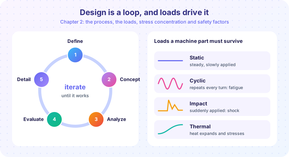
The big picture
Four ideas run through the chapter.
- The process. Requirements, concepts, sizing and evaluation, repeated until the design is good enough and documented.
- The loads. Static, cyclic, impact and thermal loads each cause different failures. You need to know which ones your part sees, and how they travel through the machine from the point of application to the foundation.
- Stress concentration. Holes, grooves and sudden changes in size raise the local stress above the nominal value by a factor
Kt, often between 1.5 and 3. - Safety. A factor of safety (or a target reliability) covers the unknowns. Too small is dangerous; too large is wasteful.
The design loop
Know your loads
Load paths
Stress concentration
Safety and reliability
What each lesson covers
| Lesson | What you can do afterwards |
|---|---|
| The design process and requirements | Write measurable requirements, generate concepts and iterate on a size |
| Loads and load paths | Classify loads, trace forces through a machine and estimate impact loads |
| Stress concentration | Use Kt for a plate with a hole and a shaft shoulder, and reduce it by design |
| Safety factors and reliability | Choose a design factor and estimate the probability of failure |
| Chapter review | Test yourself on the whole chapter |
How the pieces connect
The four ideas of this chapter are a sequence. The process tells you when to calculate; it starts with requirements, because a requirement such as "life of 10,000 lifts" or "no rope slipping" later decides which loads matter and how large the safety factor must be. Next you must know the loads. A load is not a single number: it has a type (static, cyclic, impact or thermal), a size and a path through the machine, and each type points to a different failure. Then comes the geometry. Holes, shoulders and keyways multiply the nominal stress locally, which is the difference between a part that is fine on paper and one that cracks at a fillet. Finally the safety factor turns all the remaining uncertainty into a margin, and reliability theory shows what that margin really buys.
If you remember only one sentence, remember this one: every number in a design has an uncertainty, and the designer's job is to know where the largest ones hide. Loads are usually the biggest unknown, followed by stress concentration and material scatter.
How to study this chapter
Work the lessons in order, because each one feeds the next: the requirements fix the loads, the loads give the stresses, the stresses are multiplied by concentration factors, and the result is compared with strength through a factor of safety. In every lesson, run the simulations and change one input at a time. Notice which changes matter a lot (a hole in a plate triples the peak stress; a suddenly applied load doubles it) and which hardly matter at all. That sensitivity sense is what experienced designers have and beginners lack.
A first calculation: loads multiply
A 200 kg motor sits on a platform. The weight is W = 200 × 9.81 = 1,962 N. If the same motor is lowered by a crane and its cable jerks, the platform may experience a short load of twice that, because a suddenly applied load produces double the static deflection. If the platform also has a hole, the local stress may be three times the average stress around the hole. Multiply the effects: 2 × 3 = 6 times the number from a simple weight divided by area. This is why a design that looks safe on paper can fail: the paper calculation left out multipliers that the real world supplies.
Press Run (or Ctrl + Enter) to see the result here.
Program input · what you'd type while the program runs
Type the answers before you press Run, one per line. Each time the program reads a line (with input()), it gets the next line from this box.
Check your understanding
Quick check · 4 questions
of 4 answered You scored / 4 · perfect!
-
1. Which of these is NOT one of the four load types listed in the overview?
The chapter groups loads as static, cyclic, impact and thermal. -
2. What does the factor Kt describe?
Kt is the theoretical stress concentration factor: peak stress divided by nominal stress. -
3. A suddenly applied load, compared with the same load applied slowly, produces about what deflection and stress?
For a linear elastic part a load applied suddenly (without impact velocity) produces twice the static deflection and stress. -
4. Why is the design process a loop rather than a straight line?
Sizing is circular, so we guess, compute and adjust.
Summary
- Chapter 2 covers the design process, loads, stress concentration and safety.
- Real parts see combined effects: loads multiply and stress concentrates.
- Safety factors and reliability turn uncertainty into margins.
Track your progress
Create a free account to tick off lessons and pick up where you left off on any device.
of Machine Design lessons completed