


















Lesson 29 of 46 · Bearings and Springs
Journal bearings and lubrication
Understand how a journal bearing carries a shaft on an oil film: the wedge effect, lubrication regimes, the Stribeck curve, Petroff friction and a worked power-loss example.
A journal bearing is the simplest bearing there is: a smooth shaft (the journal) turning inside a smooth cylindrical sleeve, with oil between them. Car engines have them on the crankshaft, turbines and big electric machines use them, and there are thousands in any factory. A well-designed journal bearing can run for decades with no wear at all, because the metal surfaces never touch. They are quiet, they damp vibration, they carry large shock loads and they cost little.
The curious thing is how they work. The shaft does not sit in the middle of the bore. It floats off-center on a thin film of oil, and the film is self-generated by the shaft's own rotation. Understanding this single mechanism, hydrodynamic lubrication, explains almost everything about journal bearings, including why they have high friction at start-up and why they fail when oil gets too hot.
What you will learn
- Explain how a rotating shaft generates a load-carrying oil film (the wedge effect).
- Distinguish boundary, mixed and hydrodynamic lubrication using the Stribeck curve.
- Use the Petroff equation to estimate friction torque and power loss.
- Name the design variables of a journal bearing: clearance ratio, length-to-diameter ratio, viscosity and Sommerfeld number.
Key terms
- Radial clearance
c: the difference between the bearing radius and the journal radius. Typically aboutr / 1000. - Eccentricity
e: the distance between the centers of the shaft and bearing. The eccentricity ratioε = e / cgoes from 0 (centered) to 1 (touching). - Minimum film thickness
h0: the thinnest oil layer,h0 = c (1 − ε). - Dynamic viscosity
μ: the oil's resistance to flow, in Pa·s. It falls steeply as the oil heats up. - Sommerfeld number
S: the dimensionless groupS = (r/c)² μN / Pthat describes the operating point.
Why a shaft floats: the wedge
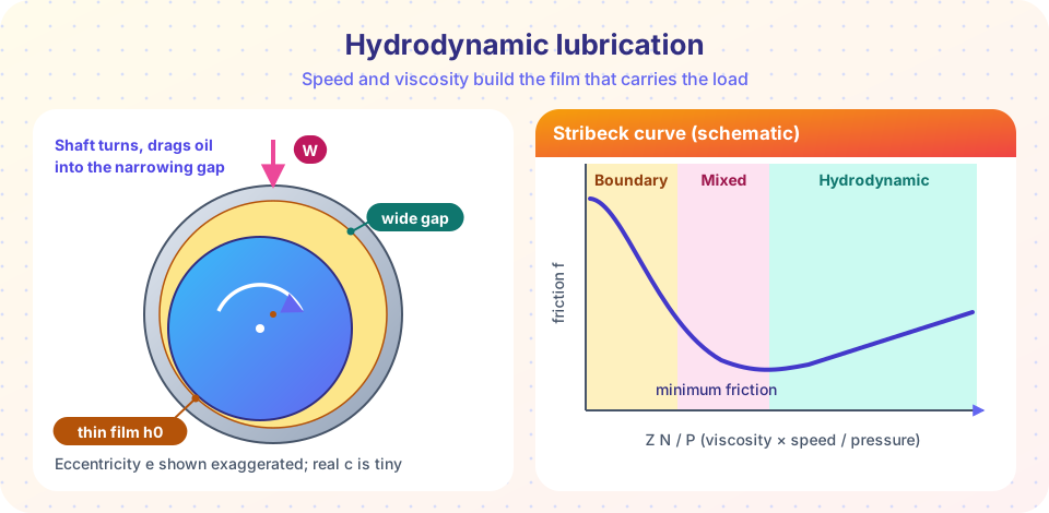
At rest, the shaft sits on the bottom of the bearing, metal to metal. When it starts to turn, friction first drags the shaft up the side of the bore a little. Oil sticks to both surfaces (the "no-slip" condition), so the rotating shaft pulls oil along with it into the narrow gap that forms below and to one side of the contact. A fluid squeezed into a converging wedge must build up pressure to get through, in the same way that water pressurizes when you push it through a narrowing pipe. This pressure lifts the shaft, and since the pressure acts all around the film, it pushes the shaft sideways as well, so the shaft center moves in a curve as the speed increases, from the bottom of the bore towards the center.
Osborne Reynolds explained this in 1886 with the lubrication equation that carries his name. The result is that the film pressure is highest just before the minimum film thickness and can reach tens of megapascals even though the oil is fed in at almost no pressure. In a good bearing the film is only some micrometers thick at its thinnest, many times thicker than the roughness of the surfaces, so the metals never touch.
You can see why three things matter: speed (more oil dragged in), viscosity (thicker oil builds more pressure) and load (a bigger load squeezes the film thinner). They combine into one group, μ N / P, with the shaft speed N in revolutions per second and the bearing pressure P = W / (2 r l) (load divided by projected area, where l is the bearing length).
The Stribeck curve: three regimes
Plot the friction coefficient against μN/P for a bearing, and you get the Stribeck curve shown in the picture above.
| Regime | Where | What happens | Friction coefficient |
|---|---|---|---|
| Boundary | Very slow or heavily loaded, at start-up and stopping | Metal contact, with thin molecular layers of additives and oxides | About 0.05 to 0.2 |
| Mixed | Intermediate | Some load on the film, some on touching asperities | Falls steeply |
| Hydrodynamic | High speed, light load, thick oil | Full film, no contact | Often 0.001 to 0.01, rising slowly with μN/P |
A bearing is designed to run in the hydrodynamic region, a safe distance to the right of the friction minimum. Start-ups and shutdowns pass through the mixed and boundary regimes and cause nearly all of the wear, so machines that start and stop often (like car engines) need bearing materials that tolerate a little contact, such as a soft babbitt (tin or lead based alloy) lining or a bronze alloy, which also embeds small dirt particles and survives brief starvation.
The Petroff equation
In 1883 N. P. Petroff made the simplest possible model: a concentric shaft (no eccentricity, no load) turning in a bearing with a uniform oil film of thickness c. The shear stress in the oil is τ = μ U / c, with the surface speed U = 2π r N. The friction force on the shaft is τ times the area 2π r l, and the torque is that force times r:
T = 4π² μ N l r³ / c
Dividing the torque by W r (with W = 2 r l P) gives the friction coefficient
f = 2π² (μN / P) (r / c)
So, in the hydrodynamic region the friction coefficient increases in proportion to μN/P, the straight line on the right of the Stribeck curve. The equation is exact only for a lightly loaded bearing, but it gives a remarkably good estimate of friction for ordinary loads, and shows quickly what matters: a thin film (small c) is more friction, while a larger clearance reduces friction but also load capacity and stiffness.
The power lost in friction is T ω with ω = 2π N. Nearly all of this heat enters the oil, and the temperature at which the bearing settles is set by the balance between this heat and what the oil flow and the housing carry away.
Worked example
A journal has radius r = 25 mm, bearing length l = 50 mm and radial clearance c = 0.025 mm (so r/c = 1000). It carries W = 2.5 kN at 1800 rpm (N = 30 rev/s). The oil's viscosity at its operating temperature is μ = 0.02 Pa·s (illustrative).
- Bearing pressure:
P = W / (2 r l) = 2500 / (2 × 0.025 × 0.050) = 1.0 MPa. μN / P = 0.02 × 30 / (1.0 × 10⁶) = 6.0 × 10⁻⁷.- Friction coefficient:
f = 2π² × 6.0 × 10⁻⁷ × 1000 = 0.0118. - Torque:
T = f W r = 0.0118 × 2500 × 0.025 = 0.74 N·m. - Power loss:
T ω = 0.74 × 188.5 = 139 W. - Sommerfeld number:
S = (r/c)² μN / P = 10⁶ × 6.0 × 10⁻⁷ = 0.6.
139 W is a lot of heat for such a small bearing: you can feel it as warmth. Doubling the speed doubles the power loss at fixed oil temperature. In practice, you also have to check that the oil film is thick enough, and that the oil does not overheat (which makes it thinner and drops μ, so the film shrinks while the load stays the same).
Design variables and practical rules
The detailed design of a hydrodynamic bearing uses charts or software based on Reynolds's equation, for example the Raimondi and Boyd charts, which give the minimum film thickness, the friction and the oil flow as functions of S and the length-to-diameter ratio l/d. Some common values and rules:
- Clearance ratio
c / ris about 0.001, which means a diametral clearance of about one thousandth of the journal diameter; it must be matched to the manufacturing tolerances. l / dis usually between 0.5 and 1.5. Short bearings lose oil from their ends and carry less; long bearings are sensitive to misalignment.- Viscosity is the main knob. Oil grades (ISO VG 32, 46, 68, ...) refer to the viscosity at 40 °C, and viscosity drops by a factor of three or more between 40 °C and 80 °C. Always use the viscosity at the operating temperature.
- Minimum film thickness must exceed several times the combined roughness of the shaft and the bearing, plus an allowance for misalignment and deflection.
- Oil supply: oil is fed at the point of lowest pressure, usually through an axial groove or a hole, never in the highly loaded region.
Journal versus rolling bearings
| Journal bearing | Rolling bearing | |
|---|---|---|
| Friction at start | High (boundary) | Low |
| Friction at speed | Low (film) | Low |
| Life | Practically unlimited in full-film regime | Limited by fatigue |
| Shock and vibration | Very good | Moderate |
| Space | Small radial height | Larger |
| Needs | Oil supply, cleaning | Little maintenance |
Common misconceptions
- "The oil is pumped in at high pressure to lift the shaft." In a hydrodynamic bearing the shaft itself generates the pressure by dragging oil into the wedge. Pressurized oil is used only in hydrostatic bearings and for start-up lifting.
- "The shaft is centered when it is floating." It sits off-center, and that eccentricity is what creates the wedge. A perfectly centered shaft carries no load.
- "Thicker oil is always better." A thicker oil carries more load, but also gives more friction and heat. The best viscosity is a compromise.
- "Friction goes up when you start to turn faster." It first goes down, through the mixed regime, then slowly rises again at high
μN/P.
Try it
The first TryIt is a Petroff calculator. It repeats the worked example and then shows how speed and viscosity change friction and power loss.
Press Run (or Ctrl + Enter) to see the result here.
Program input · what you'd type while the program runs
Type the answers before you press Run, one per line. Each time the program reads a line (with input()), it gets the next line from this box.
The second TryIt draws a schematic Stribeck curve. The hydrodynamic line is the Petroff equation. The boundary part is an assumed friction coefficient of 0.1 and the blend between them is a made-up smooth function, so treat the shape as a picture, not as data.
Press Run (or Ctrl + Enter) to see the result here.
Program input · what you'd type while the program runs
Type the answers before you press Run, one per line. Each time the program reads a line (with input()), it gets the next line from this box.
Check your understanding
Quick check · 5 questions
of 5 answered You scored / 5 · perfect!
-
1. What generates the pressure that carries the load in a hydrodynamic journal bearing?
The no-slip condition makes the rotating journal pull oil into the narrowing gap, which builds the pressure. -
2. A journal of radius 20 mm and bearing length 40 mm carries 1600 N. What is the bearing pressure P = W/(2 r l)?
P = 1600 / (2 × 0.020 × 0.040) = 1600 / 0.0016 = 1.0 MPa. -
3. At which stage of operation is a hydrodynamic bearing most at risk of wear?
At very low speed the film cannot form, so the surfaces touch (boundary and mixed lubrication). -
4. Why does oil temperature matter so much for a journal bearing?
Viscosity falls steeply with temperature, so a hot bearing has less μ, a thinner film and more risk of contact. -
5. According to the Petroff equation, what happens to the friction coefficient if the speed doubles (everything else fixed)?
f = 2π² (μN/P)(r/c) is proportional to N, so doubling N doubles f in the hydrodynamic region.
Summary
- A journal bearing carries the shaft on an oil film generated by the shaft's rotation in a converging wedge.
- The Stribeck curve has boundary, mixed and hydrodynamic regimes; run in the hydrodynamic regime, away from the minimum.
- Petroff:
T = 4π² μ N l r³ / candf = 2π² (μN/P)(r/c); power loss isT ωand ends up as heat in the oil. - Key design variables: clearance ratio about 0.001,
l/dfrom 0.5 to 1.5, viscosity at operating temperature and the Sommerfeld number. - Start-stop cycles cause most of the wear, so choose a bearing material that tolerates brief contact.
Track your progress
Create a free account to tick off lessons and pick up where you left off on any device.
of Machine Design lessons completed