


















Lesson 19 of 46 · Shafts and Fasteners
Keys, Splines and Critical Speed
Size parallel keys for shear and bearing stress, compare keys, splines and press fits, and estimate the critical speed of a shaft so it never runs in resonance.
A shaft has to deliver its torque to something: a gear, a pulley, a sprocket, a flywheel. Somewhere there must be a connection that carries that torque from the shaft into the hub. The oldest and most common solution is the key, a small block that sits half in a groove in the shaft and half in a groove in the hub. Keys are simple, cheap and easy to remove, but they have limits, and they concentrate stress at the groove.
A second, quite different issue concerns the shaft itself. Every shaft with mass on it has a natural frequency of lateral vibration. If it spins at the speed matching that frequency, it whirls: deflection grows violently, and bearings or the shaft fail. The speed at which this happens is the critical speed, and keeping clear of it is part of the design. This lesson covers both topics.
What you will learn
- The ways of connecting a hub to a shaft and their trade-offs.
- How to check a parallel key for shear and bearing stress, and size its length.
- How to compute the critical speed of a shaft with one or more masses.
- How to keep the running speed away from resonance.
Key terms
- Parallel key: a rectangular key of constant section, defined by width
b, heighthand lengthl. - Keyway (keyseat): the groove cut in the shaft or the hub; it concentrates stress.
- Spline: a series of teeth on the shaft that mate with grooves in the hub; carries more torque than a key.
- Critical speed: a rotational speed that coincides with a natural frequency of lateral vibration.
- Whirling: the large synchronous deflection of a shaft running at its critical speed.
Ways to attach a hub
| Method | Strengths | Weaknesses |
|---|---|---|
| Parallel key | Cheap, standard, easy to assemble | Weakens the shaft, loose fit gives backlash, stress at keyway |
| Splines | Carry high torque, allow axial sliding, many teeth share load | More expensive, notch effect |
| Press or shrink fit | No keyway, good concentricity, high torque by friction | Hard to disassemble, fretting, needs tight tolerances |
| Tapered fit with key or nut | Self-centering, easy removal | Machining cost |
| Set screw | Simple, for light duty | Damages the shaft; only for small loads |
| Clamping hub, taper-lock bushing | No keyway, adjustable | Cost, size |
The choice depends on torque, speed, whether axial movement is needed, and how often the part is removed. Reversing or shock loads loosen keys and favor splines or interference fits.
Sizing a parallel key
Standard keys are chosen by shaft diameter. A typical metric series (the ISO and DIN family, width × height in mm) is:
| Shaft diameter d (mm) | Key b × h (mm) |
|---|---|
| over 12 up to 17 | 5 × 5 |
| over 17 up to 22 | 6 × 6 |
| over 22 up to 30 | 8 × 7 |
| over 30 up to 38 | 10 × 8 |
| over 38 up to 44 | 12 × 8 |
| over 44 up to 50 | 14 × 9 |
| over 50 up to 58 | 16 × 10 |
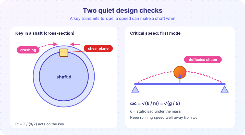
The standard fixes b and h; the designer chooses the length l so that the key does not fail. A key can fail in two ways, as the picture shows.
Shear along the interface between shaft and hub. The force on the key is the torque divided by the shaft radius, F = T / (d/2) = 2T/d, and it acts over the area b × l:
τ = F / (b l)
Bearing (crushing) on the side of the key. The side face is only half the key height in contact with the shaft (the other half bears on the hub), so the contact area is (h/2) × l:
σb = F / ((h/2) l) = 2 F / (h l)
The design uses the key material's yield strength with a factor of safety: n = Ssy/τ where Ssy = 0.577 Sy, and n = Sy/σb. Keys are often made of a softer steel (such as 1020 cold-drawn, Sy = 390 MPa) so that the key, rather than the shaft or the hub, is the part that sacrifices itself in an overload.
Example. A 40 mm shaft carries T = 600 N·m. The key is 12 × 8 mm of 1020 CD steel. Then F = 2 × 600,000 / 40 = 30,000 N. For a safety factor n = 2: the allowable bearing stress is 390/2 = 195 MPa, so l ≥ F / ((h/2) × 195) = 30,000 / (4 × 195) = 38.5 mm. The allowable shear stress is 0.577 × 390/2 = 112.5 MPa, so l ≥ F / (b × 112.5) = 30,000 / (12 × 112.5) = 22.2 mm. Bearing governs, and the standard length is 40 mm. For a square key, and for most keys, bearing governs. It also fits a hub of length about 1 to 1.5 times the shaft diameter, which is typical.
Press Run (or Ctrl + Enter) to see the result here.
Program input · what you'd type while the program runs
Type the answers before you press Run, one per line. Each time the program reads a line (with input()), it gets the next line from this box.
Keyways and fatigue
A keyway is a notch. An end-milled keyseat has a stress concentration for bending of about Kt = 2 and for torsion about Kt = 3, higher at the ends. A sled-runner keyseat (cut with a disc cutter) has a smoother end and a lower Kt. If the keyway lies near the highest moment of the shaft, it usually dictates the diameter in the fatigue calculation. The remedies: move the keyway away from the critical section, use a longer fillet, use a spline or an interference fit, or increase the diameter.
Critical speed
Picture a shaft with a heavy disc in the middle, spinning. No disc is perfectly balanced, so its center of mass is a little off the axis. The shaft deflects slightly, which moves the mass further from the axis, which increases the centrifugal pull, which increases the deflection. At low speeds the shaft stays stable. As the speed rises toward the natural frequency of lateral vibration, the deflection grows rapidly, and at exactly that speed it is limited only by damping. Above it, the shaft stabilizes again, with the disc turning about its own center of mass (self-centering). The speed at the peak is the critical speed ωc.
For a single mass m on a massless shaft with lateral stiffness k, the natural frequency is ωc = √(k/m). Since the static deflection under the weight is δ = m g / k, this is also
ωc = √(g / δ)
where δ is the static sag in the same units as g (mm and 9,810 mm/s², or m and 9.81 m/s²). For a simply supported shaft with a central mass, δ = m g L³ / (48 E I).
Example. A 30 mm steel shaft, 400 mm between bearings, with a 12 kg disc at the middle. I = π × 30⁴/64 = 39,761 mm⁴, and δ = 12 × 9.81 × 400³ / (48 × 207,000 × 39,761) = 0.0191 mm. So ωc = √(9,810 / 0.0191) = 717 rad/s, which is 6,850 rpm. A motor at 1,500 rpm is far below it; a spindle at 6,000 rpm is dangerously close.
Several masses: Rayleigh and Dunkerley
With several masses wi (weights) at points where the static deflection (under all the weights together) is yi, Rayleigh's method gives an estimate of the first critical speed:
ωc² = g · Σ(wi yi) / Σ(wi yi²)
It slightly overestimates the true value. Dunkerley's equation gives a slightly underestimated value: 1/ωc² ≈ 1/ω1² + 1/ω2² + … + 1/ωs², where ωi is the critical speed with only the i-th mass present and ωs is that of the shaft alone. Including the mass of the shaft itself matters for long shafts.
Staying away from resonance
The rule of thumb is to keep the operating speed at least about 20 to 30% below the first critical speed (a subcritical shaft, most machines) or well above it (a supercritical shaft, such as many turbines, which must pass through it quickly). Raising the critical speed means making the shaft stiffer and lighter: a larger diameter (the stiffness grows with d⁴), shorter spans, or moving the masses closer to the bearings. Damping and balancing reduce the peak but do not move it.
Press Run (or Ctrl + Enter) to see the result here.
Program input · what you'd type while the program runs
Type the answers before you press Run, one per line. Each time the program reads a line (with input()), it gets the next line from this box.
Notice that the peak sits at r = 1 for small damping and that above r ≈ 1.4 the response levels off at about 1: the shaft runs smoothly again, but only after passing through the peak. More damping flattens the peak, which is why machines that must pass through a critical speed (turbines, centrifuges) use damped bearings.
Common misconceptions
- "A stronger shaft has a higher critical speed." The critical speed depends on stiffness and mass, not on strength. A heat-treated shaft of the same size has the same critical speed.
- "A key transmits torque by friction." A key transmits torque by direct contact (bearing) on its side and shear in its body. Friction from the fit is a bonus.
- "Shear is the main key check." For standard keys, bearing stress on the side usually governs.
Check your understanding
Quick check · 5 questions
of 5 answered You scored / 5 · perfect!
-
1. A 50 mm shaft transmits 500 N·m. What is the tangential force on the key?
F = 2T/d = 2 × 500,000 N·mm / 50 mm = 20,000 N. -
2. A 10 × 8 key of length 40 mm carries F = 16 kN. What is the bearing stress?
σb = F / ((h/2) l) = 16,000 / (4 × 40) = 100 MPa. -
3. Which key stress usually governs the length of a standard key?
The contact area on the side is only h/2 × l, so bearing stress is typically larger than the safety margin allows before shear is. -
4. A shaft's static sag under its disc is 0.05 mm. What is its critical speed (g = 9,810 mm/s²)?
ωc = √(g/δ) = √(9,810 / 0.05) = √196,200 = 443 rad/s. -
5. How can you raise the critical speed of a shaft?
Critical speed depends on stiffness over mass, and stiffness grows strongly with diameter and falls with span.
Summary
- Parallel keys: standard
b × hfrom the shaft diameter;F = 2T/d; checkτ = F/(b l)andσb = 2F/(h l); bearing usually governs. - Keyways concentrate stress (
Ktabout 2 for bending, 3 for torsion); splines or fits avoid them. - Critical speed:
ωc = √(k/m) = √(g/δ); Rayleighωc² = g Σwy/Σwy²for several masses. - Stay 20 to 30% away from the critical speed; stiffness and mass decide it, not strength.
Track your progress
Create a free account to tick off lessons and pick up where you left off on any device.
of Machine Design lessons completed