


















Lesson 23 of 46 · Gears
Gear geometry and ratios
Learn the involute tooth, module, pitch diameter, pressure angle, contact ratio and minimum tooth count, then size a gear pair and build a gear train.
Before you can ask whether a gear is strong enough, you have to know what it looks like. Gear geometry is a small set of definitions and relationships, and once you know them you can read a gear drawing, specify a pair that meshes, and predict speed, center distance and tooth shape. Everything in the following lessons (forces, stresses, bearings) uses the diameters you calculate here.
The big idea is simple. Two gears should behave like two smooth wheels rolling on each other without slipping. The teeth exist only to stop slipping, and they must be shaped so that they do not disturb that smooth rolling. The curve that achieves this is called the involute, and nearly all gears in the world use it.
What you will learn
- Read and use the pitch circle, module, addendum, dedendum and pressure angle.
- Explain why the involute curve gives a constant speed ratio.
- Calculate the center distance, pitch-line velocity and contact ratio of a spur pair.
- Recognize undercutting and find the minimum tooth count.
- Work out the speed ratio and direction of a gear train.
Key terms
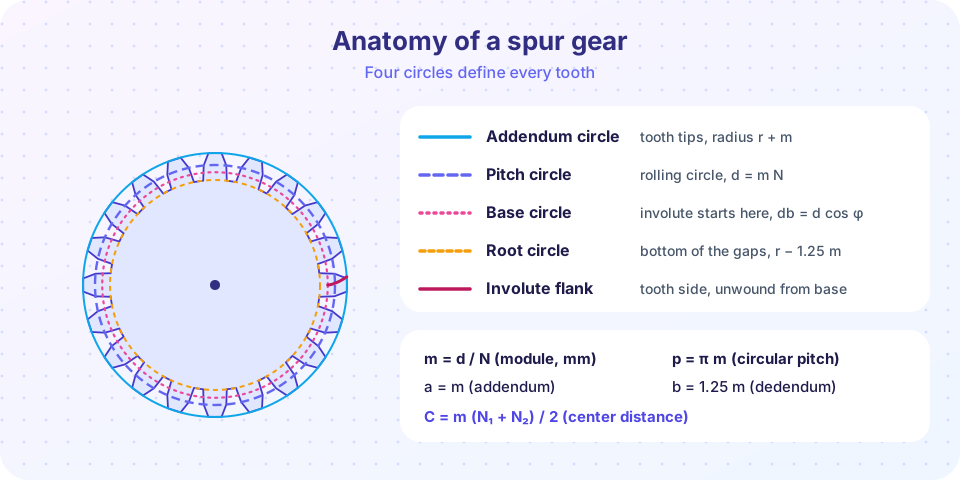
- Pitch circle: the circle on which a gear rolls against its mate. Its diameter is the pitch diameter
d = m N. - Module
m: pitch diameter divided by the number of teeth, in millimeters. Largermmeans bigger teeth. - Pressure angle
φ: the angle between the line of action and the common tangent of the pitch circles. 20° is the modern standard. - Addendum / dedendum: tooth height above / below the pitch circle.
- Contact ratio: the average number of tooth pairs in contact.
The pitch circle and the module
Imagine replacing two gears by two smooth cylinders that roll on each other. Their contact radii are the pitch radii r1 and r2, and the surface speeds at the contact point are equal, so ω1 r1 = ω2 r2. This gives the speed ratio directly from the radii, or, since tooth count is proportional to diameter, from the teeth: ω1 / ω2 = N2 / N1.
To make a tooth size independent of how many teeth a gear has, we define the module m = d / N (in mm). A gear with 40 teeth and module 3 has a pitch diameter of 120 mm. The circular distance from one tooth to the next, measured on the pitch circle, is the circular pitch p = π m. Gears in inch-based catalogs use the diametral pitch P = N / d in teeth per inch; the conversion is m = 25.4 / P. We use module throughout, with the preferred first-choice values 1, 1.25, 1.5, 2, 2.5, 3, 4, 5, 6, 8 and 10 mm. Using standard values means cutters and spare gears are available.
For a standard full-depth tooth, the proportions follow from m:
| Quantity | Symbol | Value |
|---|---|---|
| Addendum | a |
m |
| Dedendum | b |
1.25 m |
| Whole depth | h |
2.25 m |
| Clearance | c |
0.25 m |
| Tooth thickness on the pitch circle | t |
π m / 2 |
| Tip (addendum) diameter | da |
d + 2m |
| Root diameter | df |
d − 2.5 m |
Two gears mesh only when they have the same module and the same pressure angle. Their center distance is then
C = (d1 + d2) / 2 = m (N1 + N2) / 2
and the pitch-line velocity, which sets lubrication and noise, is v = π d n / 60 with d in meters and n in rpm, giving m/s.
Why the involute?
Take a flat strip of paper wrapped around a circular can, and pull it off while keeping it taut. The end of the strip draws a curve, the involute of the can's circle. In gear language the can is the base circle, with diameter db = d cos φ. The tooth flank is a piece of that curve.
The profile has a remarkable property. When two involute teeth push against each other, the contact point always slides along one straight line, the line of action. This line is tangent to both base circles and passes through the pitch point, which is where the pitch circles touch. Because the common normal of the teeth always passes through the pitch point, the fundamental law of gearing is satisfied: the speed ratio stays constant, whatever the position of the teeth. A constant ratio means smooth torque and low vibration.
Two practical bonuses explain why the involute won. First, if you move the gears slightly apart (a mounting error, thermal growth), the base circles do not change, so the ratio is still exact. Second, a single rack-shaped cutter, with straight flanks, can cut involute gears of any tooth count of one module.
The angle between the line of action and the common tangent at the pitch point is the pressure angle φ. Standard value: 20°. Older gears used 14.5°, which have a smoother mesh but weaker, more undercut teeth. A larger angle such as 25° makes a stronger tooth but pushes the bearings harder, as you will see in the next lesson.
Contact ratio: how many teeth share the load
If only one pair of teeth were in contact at any moment, each pair would hand over the load abruptly. In a good mesh the next pair engages before the previous one leaves. The contact ratio measures this overlap. For external spur gears it is the length of the contact path divided by the base pitch:
CR = [ √(ra1² − rb1²) + √(ra2² − rb2²) − C sin φ ] / (π m cos φ)
Here ra is the tip radius and rb the base radius of each gear. A value of 1.67 means two pairs share the load about two-thirds of the time and one pair a third of the time. Aim for at least about 1.2, and preferably above 1.4 for quiet running. Gears with more teeth have a higher contact ratio, which is one reason many small teeth run quieter than a few big ones.
Undercutting and the minimum tooth count
Below the base circle there is no involute. If a pinion has too few teeth, the tip of the cutter (or of the mating gear's tooth) digs under the root of the pinion tooth. This undercut weakens the tooth exactly where the bending stress is highest. The smallest tooth count that avoids it for a full-depth 20° gear is
N_min = 2 / sin² φ ≈ 17.1 for φ = 20°
So in practice 17 or 18 teeth is the lower limit for a standard pinion, and a few teeth fewer can be tolerated with a modified ("profile-shifted") tooth. A 25° pressure angle lowers the limit to about 11 teeth.
Worked example: sizing a first pair
A motor delivers 1450 rpm and the machine needs roughly 360 rpm, so the ratio is about 4. Choose a pinion N1 = 20 and a gear N2 = 80, with module m = 2.5 mm and φ = 20°.
- Pitch diameters:
d1 = 2.5 × 20 = 50 mm,d2 = 2.5 × 80 = 200 mm. - Center distance:
C = (50 + 200)/2 = 125 mm. - Output speed:
1450 × 20/80 = 362.5 rpm. - Pitch-line velocity:
v = π × 0.050 × 1450 / 60 = 3.80 m/s. - Tip diameters:
da1 = 55 mm,da2 = 205 mm; root diameters43.75 mmand193.75 mm.
The calculator below repeats the work and also finds the contact ratio.
Gear trains
One pair rarely gives enough ratio. A simple train connects gears in a row, each shaft carrying one gear. The ratio is set only by the first and last gears; the middle gears, called idlers, change the direction but not the ratio. A compound train puts two gears on the same shaft, so each stage multiplies the ratio:
ratio = (N2 / N1) × (N4 / N3) × ...
With 20 → 60 teeth followed by 18 → 54 teeth, each stage is 3, and the total reduction is 3 × 3 = 9. A 1450 rpm input becomes 161 rpm at the output. Each external mesh reverses the direction of rotation, so after k external meshes the direction is multiplied by (−1)^k; two meshes give the same direction as the input. Compound trains are compact: reaching a ratio of 9 with one pair would need a gear 9 times the pinion diameter.
Common misconceptions
- "The pitch diameter is the outside diameter." The outside (tip) diameter is
m (N + 2). Drawings state both; mixing them up gives a center distance that is wrong by one module. - "Any two gears with the same number of teeth mesh." Teeth only mesh if the module and pressure angle match as well.
- "A larger module is always better." A larger module gives a stronger tooth, but fewer teeth for the same diameter, a lower contact ratio and more noise.
- "An idler changes the ratio." An idler only reverses the direction and adds a bearing load. The ratio depends on the first and last gears alone.
Try it
The first TryIt is a spur gear calculator. Edit the module and tooth counts, and check the contact ratio against the guideline of about 1.2.
Press Run (or Ctrl + Enter) to see the result here.
Program input · what you'd type while the program runs
Type the answers before you press Run, one per line. Each time the program reads a line (with input()), it gets the next line from this box.
The second TryIt draws the actual involute tooth outline from the base circle formula. The half-thickness angle of the tooth at radius r is π/(2N) + inv φ − inv α, where inv x = tan x − x and cos α = rb / r.
Press Run (or Ctrl + Enter) to see the result here.
Program input · what you'd type while the program runs
Type the answers before you press Run, one per line. Each time the program reads a line (with input()), it gets the next line from this box.
Check your understanding
Quick check · 5 questions
of 5 answered You scored / 5 · perfect!
-
1. A gear has 36 teeth and module 4 mm. What is its pitch diameter?
d = m N = 4 × 36 = 144 mm. The tip diameter would be 152 mm (m (N + 2)), which is a common trap. -
2. Two gears with module 3 mm have 24 and 60 teeth. What is the center distance?
C = m (N1 + N2) / 2 = 3 × 84 / 2 = 126 mm. -
3. Why does the involute profile give a constant speed ratio?
The common normal at every contact point passes through the pitch point. That is the fundamental law of gearing. -
4. What is the smallest number of teeth that avoids undercutting for a standard full-depth 20 degree pinion?
N_min = 2 / sin²(20°) ≈ 17.1. -
5. In a compound train with stage ratios 3 and 3, the input is 1800 rpm. What is the output speed?
The total ratio is 3 × 3 = 9, so the output is 1800 / 9 = 200 rpm.
Summary
- The pitch circle is the rolling circle;
d = m N, and meshing gears share module and pressure angle. C = m (N1 + N2) / 2,v = π d n / 60,da = m (N + 2),df = m (N − 2.5).- The involute keeps the speed ratio constant because contact slides along a straight line of action through the pitch point.
- Contact ratio should be about 1.2 or higher; fewer than about 17 teeth at 20° causes undercutting.
- In a train, the ratio is the product of the stage ratios and each external mesh reverses the direction.
Track your progress
Create a free account to tick off lessons and pick up where you left off on any device.
of Machine Design lessons completed