


















Lesson 24 of 46 · Gears
Tooth forces and bending strength
Turn power into tooth force, then check a spur gear for bending with the Lewis equation and for surface fatigue with Hertz contact stress, with worked numbers.
A gear tooth is a short, stubby beam that is loaded on one flank, over and over, millions of times. Two things can go wrong. The tooth can snap at its root, where the bending stress is highest, or its surface can pit and flake, where two steel flanks press on each other with enormous local pressure. A gear designer checks both. To do so, you first have to know how big the force is and in which direction it acts.
In this lesson you will convert a motor's power into the force on a tooth, split that force into useful and wasted parts, and then use two classic stress models: the Lewis equation for bending and the Hertz equation for surface contact. The models are simplified, and real standards (ISO 6336 and AGMA 2001) add many correction factors, but they teach you which variables matter and in which direction to change them.
What you will learn
- Convert power and speed into torque, and torque into the tangential and radial tooth forces.
- Apply the Lewis bending equation, including the form factor and velocity factor.
- Compute Hertz contact stress between two involute flanks.
- Explain why bending stress depends on module while contact stress depends on diameter.
Key terms
- Tangential force
Wt: the component of the tooth force perpendicular to the radius. It carries the torque. - Radial force
Wr: the component along the radius. It does no work and pushes the gears apart. - Lewis form factor
Y: a number that depends on the tooth count and describes how strong the tooth shape is. - Velocity factor
Kv: increases the load to allow for impact at higher speeds. - Hertz stress: the contact pressure at the surface between two curved bodies pressed together.
From power to tooth force
Power is torque times angular speed, P = T ω. With power in kilowatts and speed in rpm, the torque in newton-meters is
T = 9550 P / n
(the 9550 is 60 000 / 2π). The tangential force on the pitch circle follows from the torque and the pitch radius:
Wt = T / (d/2) = 2 T / d or equivalently Wt = P / v
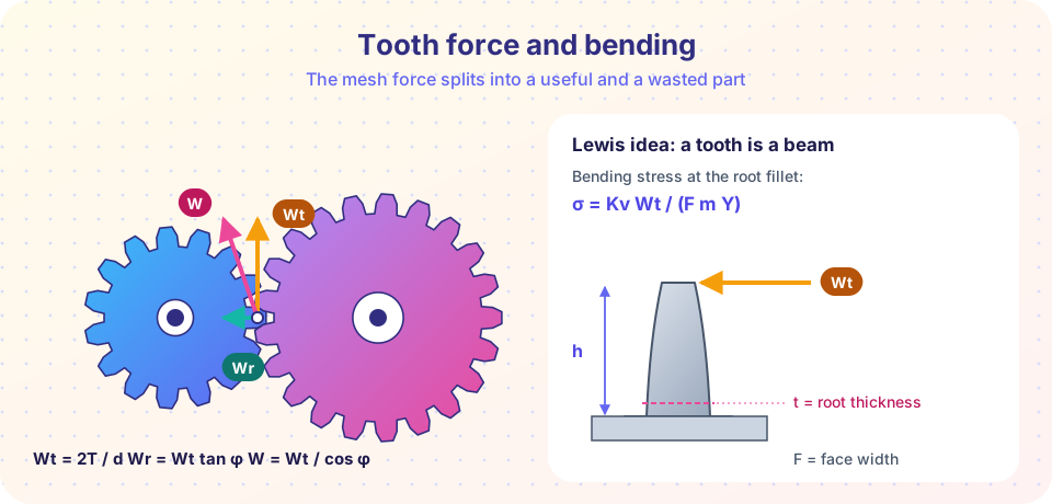
where P is in watts and v in m/s. Because the force acts at an angle (the pressure angle) to the tangent, there is also a radial component and the full tooth force:
Wr = Wt tan φ W = Wt / cos φ
For φ = 20°, Wr = 0.364 Wt and W = 1.064 Wt. The radial force is the price of the involute: it does no useful work but presses on the shafts and bearings. A larger pressure angle gives a larger Wr. Gear pairs always act with equal and opposite forces. On the driven gear, Wt points in the direction of rotation; on the driver it opposes the rotation (the driver has to push against the load). You will use these forces in later chapters to find the shaft loads and bearing reactions.
Worked example: forces
A 7.5 kW motor turns a pinion of module 2.5 mm and 20 teeth at 1450 rpm. Then:
- Torque:
T = 9550 × 7.5 / 1450 = 49.4 N·m. - Pitch diameter:
d = 2.5 × 20 = 50 mm = 0.050 m. - Tangential force:
Wt = 2 × 49.4 / 0.050 = 1976 N. - Radial force:
Wr = 1976 × tan 20° = 719 N. - Total tooth force:
W = 1976 / cos 20° = 2103 N.
How teeth fail
There are four common ways. Bending fatigue cracks the tooth at the root fillet, usually after a long life, and a missing tooth then wrecks the whole gearbox. Pitting is surface fatigue: tiny cracks under the surface grow and release small pits. Scoring (scuffing) is a welding and tearing of the surfaces when the lubricant film fails at high speed and load. Wear is gradual loss of material in a dirty or poorly lubricated mesh. Bending and pitting are the ones checked by calculation; scoring and wear are controlled by lubrication, finish and cleanliness.
The Lewis bending equation
In 1892 Wilfred Lewis made a simple idea: a gear tooth is a cantilever beam. Treat the tooth as a rectangle of width F (the face width) and thickness t at the root, loaded at its tip by Wt at height h. The bending stress in a beam is σ = M c / I, with M = Wt h, c = t/2 and I = F t³ / 12, giving
σ = 6 Wt h / (F t²)
Multiply and divide by the module m to separate size from shape:
σ = Wt / (F m Y) where Y = t² / (6 h m)
The form factor Y depends only on the tooth shape, and for a standard tooth that depends only on the tooth count. Lewis's Y is a bit smaller for few teeth because a pinion tooth is thin at the root and long.
Teeth N |
14 | 17 | 20 | 25 | 30 | 40 | 60 | 100 |
|---|---|---|---|---|---|---|---|---|
Y (20° full depth) |
0.277 | 0.303 | 0.322 | 0.340 | 0.359 | 0.389 | 0.422 | 0.447 |
Since Y increases with N, the pinion of a pair has the lower Y and is the weaker tooth, even though it carries the same force.
Two adjustments make the equation more realistic. First, teeth that meet at speed hit each other. The classical Barth velocity factor for cut gears is Kv = (6.1 + v) / 6.1 with v in m/s, and it multiplies the stress. Second, the real load depends on the driver and driven machines: a smooth electric motor driving a fan is gentle, while an engine driving a rock crusher is violent. A factor Ka, the application factor, from 1.0 up to 2 or more, covers this. The design equation is
σ = Ka Kv Wt / (F m Y) ≤ σ_allowable
Allowable bending stress for the tooth root depends on the steel and its heat treatment. For common through-hardened and case-hardened steels, handbook values range from roughly 150 MPa to well over 400 MPa; take the value from your standard, not from memory. A rule of thumb for the face width is about 8 to 16 times the module: too narrow a tooth is flimsy, too wide a tooth loads unevenly if the shafts bend.
Worked example: bending
Continue the example. Face width F = 25 mm, Y = 0.322 for N = 20, speed v = π × 0.050 × 1450 / 60 = 3.80 m/s. Then Kv = (6.1 + 3.80)/6.1 = 1.62 and, with Ka = 1:
σ = 1.62 × 1976 / (25 × 2.5 × 0.322) = 159 MPa
If the allowable stress is 200 MPa, the safety factor is 200/159 = 1.26. That is modest. In the calculator below, cutting the face width to 15 mm pushes the pinion stress to 265 MPa and the safety factor below 1, while raising the module to 3 mm lowers it to 119 MPa.
Contact stress: the Hertz model
Where two curved surfaces touch under load, the contact is not a line but a thin strip, and the pressure there is very high. Heinrich Hertz solved this for two parallel cylinders in 1881. Two involute flanks at the pitch point behave like two cylinders whose radii are the radii of curvature of the profiles, ρ = (d sin φ) / 2 for each gear. The peak pressure is
σH = Zₑ · √[ (Wt / (F cos φ)) · (1/ρ1 + 1/ρ2) ]
with Zₑ = 189.8 √MPa for steel on steel (it combines E = 206 GPa and ν = 0.3), when Wt is in newtons and lengths in mm.
For the example gears (ρ1 = 50 sin 20°/2 = 8.55 mm, ρ2 = 200 sin 20°/2 = 34.2 mm), Wt/(F cos φ) = 1976 / (25 × 0.940) = 84.1 N/mm, and 1/ρ1 + 1/ρ2 = 0.1462 mm⁻¹. So σH = 189.8 √(84.1 × 0.1462) = 666 MPa. Hardened steel gears have allowable contact stresses of roughly 500 to well over 1000 MPa, so this pair passes with a margin.
Two knobs, two failure modes
The two stresses respond to different design variables, which is the main practical lesson:
- Bending stress depends on the module
m(and onY, which depends on tooth count). A bigger tooth is stronger. - Contact stress depends on the pitch diameter and the face width but not on the module. To lower it, make the pinion bigger or the gear wider, or use harder steel.
So you pick the pinion diameter and the face width to satisfy contact, then pick the module and tooth count to satisfy bending.
Common misconceptions
- "The tooth force is
2T/din total." That is only the tangential part. The real tooth force isWt / cos φ, and the radial part loads the bearings. - "The gear with more teeth is the weaker one." The pinion has the smaller form factor and takes more load cycles per second, so it usually governs.
- "Lewis gives the exact stress." It ignores stress concentration at the fillet and load sharing between pairs. It is a first estimate; use a standard for the final design.
- "Doubling the module halves the contact stress." Contact stress does not depend on the module at all.
Try it
The first TryIt computes forces, bending and contact stress for any pair. Change the face width and the module and watch which check becomes critical.
Press Run (or Ctrl + Enter) to see the result here.
Program input · what you'd type while the program runs
Type the answers before you press Run, one per line. Each time the program reads a line (with input()), it gets the next line from this box.
The second TryIt keeps the pinion's pitch diameter constant at 60 mm and changes the tooth count (and therefore the module m = 60/N) under a fixed tooth force of 2000 N. It shows that bending stress changes strongly with the module, while the Hertz stress does not move.
Press Run (or Ctrl + Enter) to see the result here.
Program input · what you'd type while the program runs
Type the answers before you press Run, one per line. Each time the program reads a line (with input()), it gets the next line from this box.
Check your understanding
Quick check · 5 questions
of 5 answered You scored / 5 · perfect!
-
1. A pinion with a 100 mm pitch diameter transmits 5 kW at 1000 rpm. What is the tangential tooth force?
T = 9550 × 5 / 1000 = 47.75 N·m, and Wt = 2T/d = 2 × 47.75 / 0.100 = 955 N. -
2. For a 20 degree pressure angle, what is Wr in terms of Wt?
Wr = Wt tan 20° = 0.364 Wt. The 1.064 factor belongs to the total force W = Wt / cos 20°. -
3. Which variable does the Hertz contact stress NOT depend on?
Contact stress depends on the force, the face width and the radii of curvature set by the diameters. At a given pitch diameter, changing the module does not change it. -
4. Why is the pinion usually the weaker gear in bending?
The pinion tooth is thinner at the root (smaller Y), and it also sees more load cycles. The force on both teeth is the same. -
5. A designer wants to reduce the bending stress without changing the pitch diameters. What helps?
Bending stress falls with a larger module (stronger teeth) and a wider face. A smaller module makes the teeth weaker.
Summary
T = 9550 P / n,Wt = 2T/d,Wr = Wt tan φ,W = Wt / cos φ.- Lewis bending:
σ = Ka Kv Wt / (F m Y), withKv = (6.1 + v)/6.1for cut gears andYfrom the tooth count. - Hertz contact:
σH = 189.8 √[(Wt/(F cos φ))(1/ρ1 + 1/ρ2)]MPa for steel, withρ = d sin φ / 2. - Choose diameter and face width to satisfy contact; choose module and tooth count to satisfy bending.
- Standards (ISO 6336, AGMA 2001) refine these formulas with more factors; the physics is the same.
Track your progress
Create a free account to tick off lessons and pick up where you left off on any device.
of Machine Design lessons completed