


















Lesson 4 of 46 · Getting Started
Reading a building: plan, section and elevation
Learn the three standard architectural drawings, how scale and line weight work, and how to read a plan, section and elevation of a small house step by step.
A building is three-dimensional, but paper is flat. For centuries architects have solved this with a simple trick: instead of trying to draw the whole building at once in perspective, they draw it as a set of flat, measured views. Each view shows one thing clearly and accurately. Together they let a builder reconstruct the building in their head, or on site.
The three views are plan, section and elevation. Once you can read these, you can read the drawings for any building, from a garden shed to a stadium. This lesson teaches you how, using one small house shown all three ways.
What you will learn
- What plan, section and elevation each show, and what they leave out
- How scale works, and how to turn a length on paper into a real length
- Why some lines are thick and some thin, and what the hatching means
- How to match the three views to each other, element by element
Key terms
- Orthographic projection: drawing an object by projecting each point straight onto a flat surface, so parallel lines stay parallel and lengths can be measured.
- Scale: the ratio between a length on the drawing and the real length. At 1:100, 1 mm on paper is 100 mm in reality.
- Poche: the solid fill (black, gray or hatched) of material cut through by a plan or section.
- Datum: a reference level, usually ground floor, from which heights are measured.
- Elevation: a view of a building face-on from the outside, with no cut.
Plan: a horizontal slice
Imagine slicing the house with a huge knife about 1.2 to 1.5 meters above the floor, lifting off the top, and looking straight down. What you see is the plan. Everything the cut passes through is drawn with thick lines and often filled in: the walls. You also see the floor, with doors, furniture, stairs and fittings below the cut line.
On the plan you read:
- Walls as thick bands. Thickness matters: a wall drawn 300 mm thick is a different construction from one drawn 100 mm thick.
- Openings. A gap in a wall with a thin arc is a door, and the arc shows which way it swings. A gap filled with a thin double line is a window, because the cut passes through the glazing.
- Room names and sizes, usually written in the middle of each room, and sometimes the floor area.
- Stairs, drawn as lines with an arrow pointing up. The cut passes through the stair, so you often see a diagonal break line.
- A north arrow, which tells you how the building sits on the land.
- Section lines, drawn as a long dashed line with arrows and letters at the ends, showing where the section drawings have been cut.
Plans are the most useful drawing for judging how a building works: where you enter, how rooms connect, how far it is from the kitchen to the table. This is why you will meet plans again in Chapter 3, when we study circulation.
Section: a vertical slice
A section is a vertical cut through the building. Imagine slicing the house top to bottom like a loaf of bread, taking away one half and looking at the cut face. Everything the plane touches is drawn thick: floors, walls, roofs, foundations. Things behind the cut, such as the inside of the far wall, are drawn thinner.
On the section you read:
- The building's height and the floor-to-floor distance.
- How the roof sits on the walls: slope, thickness, overhang.
- The foundations and the ground line. Part of the building is below the ground, and only a section shows it.
- Interior spaces in height: a double-height hall, a loft, a sloping ceiling.
- Heights of openings. The top and bottom of each window above the floor.
The section is the best drawing for understanding structure and spatial experience. If someone gave you only one drawing to understand a cathedral, you would ask for the section. That is exactly why the Pantheon and Gothic drawings in Chapter 2 are sections.
Elevation: the face of the building
An elevation is what you would see if you stood far away, looked straight at one side of the building, and flattened the view. There is no cut, so no poche. The elevation shows:
- Doors, windows, roof shape and materials (often indicated with a little hatching or texture).
- Heights above the ground, with the ground line drawn thicker.
- Rhythm and proportion of the openings, which we study in Chapter 3.
Elevations are named by the direction they face: the south elevation is the one you see when you look north at the building from the south. In some countries they are named front, rear, left and right instead. Because the elevation has no depth, it looks flat; architects often add shadows or a figure for scale.
How the three drawings fit together
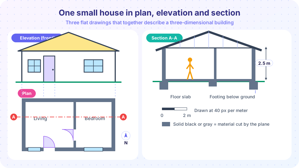
Study the illustration above. The elevation sits on top, the plan below it, and thin dashed lines run from the corners of the elevation straight down to the plan. This is orthographic projection: a point at the left edge of the door in the elevation sits at the same left position in the plan. The same door appears in all three drawings, drawn differently: a rectangle in the elevation, a gap with an arc in the plan, and a gap that is cut through only if the section passes through it.
A good habit is to read a set of drawings like a detective:
- Start with the plan. Where is the entrance? How are rooms arranged?
- Find the section line on the plan and look at the matching section. What are the heights? How does the roof meet the walls?
- Look at the elevations. How does the outside express what is inside?
- Go back to the plan with new questions. The three views answer each other.
Scale, line weight and dimensions
Drawings are not full size, so they carry a scale. A scale of 1:100 means every unit on the drawing represents 100 of the same unit in reality, so a wall that is 7.5 meters long (7,500 mm) measures 75 mm on paper. Typical scales are:
| Scale | Typical use |
|---|---|
| 1:500 or 1:200 | Site plans, large buildings |
| 1:100 | Whole-building plans, sections and elevations |
| 1:50 | Rooms and general detail |
| 1:20 or 1:10 | Construction details |
| 1:5 or 1:1 | Fine detail of joints |
Always read the scale on the drawing before you measure anything. Also check whether lengths are given in millimeters (usual in most countries) or in feet and inches (usual in the United States). Architects add dimension lines with numbers so the builder does not need to measure from the paper.
Line weight tells you what is important. The thickest line is for material cut by the plan or section: walls and floors. Medium lines show edges you see beyond the cut. Thin lines show dimensions, furniture, hatching and imaginary lines such as the dashed section line.
Common misconceptions
"A plan shows what you would see from above, like a bird's-eye photo." A plan is a slice, not a view. The roof is not shown in the plan of a floor, because the cut removes it. A drawing that shows the roof from above is a roof plan.
"You can measure any drawing with a ruler." Only if you know the scale, and only if the drawing has not been enlarged or shrunk when printed. Trust written dimensions over measurements from paper.
"The elevation is the same as a front view photograph." A photograph has perspective: near things look larger. An elevation does not, so every window of the same size is drawn the same size.
Try it
The first demo is a room designer: change the width and depth and pick a scale to see how large the room appears on paper. The second shows the same idea in numbers.
Press Run (or Ctrl + Enter) to see the result here.
Program input · what you'd type while the program runs
Type the answers before you press Run, one per line. Each time the program reads a line (with input()), it gets the next line from this box.
Check your understanding
Quick check · 5 questions
of 5 answered You scored / 5 · perfect!
-
1. At a scale of 1:100, how long on paper is a wall that is 7.5 m (7,500 mm) in reality?
Divide the real length by 100: 7,500 / 100 = 75 mm. -
2. Which drawing is made by slicing the building horizontally and looking down?
A plan is a horizontal cut, usually 1.2 to 1.5 m above the floor. A section is vertical and an elevation is a face-on view. -
3. On a plan, a gap in a wall with a thin arc usually shows what?
The arc traces the path of the door leaf, which tells you which way it opens. -
4. Why are cut walls drawn with the thickest lines?
Line weight communicates priority. The heaviest line marks material cut by the plan or section. -
5. Which drawing would you choose to understand how a roof sits on the walls?
A vertical cut shows heights, roof slope and wall thickness together, which a plan cannot.
Summary
- A plan is a horizontal slice, a section is a vertical slice, and an elevation is a face-on view with no cut.
- The three drawings are linked: a feature appears in all of them, drawn in different ways.
- Scale gives the ratio between paper and reality; at 1:100, 1 mm is 100 mm.
- Thick lines mean cut material, thin lines mean things beyond or notes; written dimensions beat measuring from paper.
- Read a set of drawings by starting with the plan, finding the section, then the elevations.
Next: Chapter 1 review
Track your progress
Create a free account to tick off lessons and pick up where you left off on any device.
of Introduction to Architecture lessons completed