


















Lesson 30 of 46 · Drawing and Representation
3D views and models
Understand isometric and axonometric drawing, one- and two-point perspective, physical models and the move from CAD to BIM, with projection maths you can run.
Plans, sections and elevations are precise but abstract: you have to assemble the building in your head. Three-dimensional drawings and models do that assembly for you. They let a client "see" a house before it exists, they let a designer test whether two volumes collide, and they let a builder understand a complicated junction.
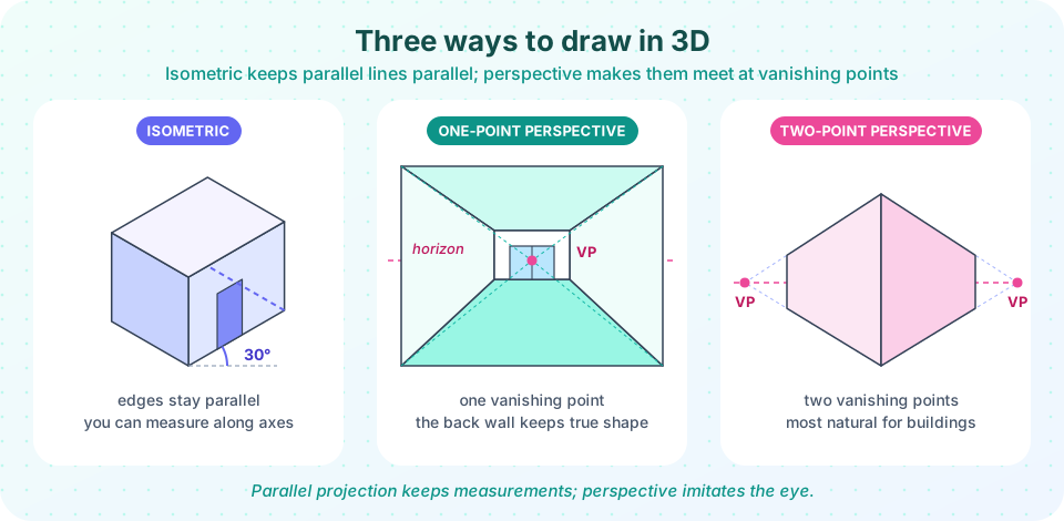
There are two families of 3D drawing, and the difference between them is the most important idea in this lesson. Parallel projections (axonometrics) keep parallel lines parallel and let you measure. Perspective makes parallel lines converge toward vanishing points and looks like what the eye sees. One serves precision, the other persuasion.
What you will learn
- How isometric and other axonometric drawings are constructed
- How one-point and two-point perspective work, and what the horizon line means
- When to choose a parallel drawing and when to choose perspective
- What physical models, CAD and BIM contribute to design and construction
Key terms
Parallel projection: a drawing in which all projection lines are parallel to one another, so that parallel edges stay parallel.
Isometric: an axonometric projection in which the three axes are equally foreshortened and drawn 120 degrees apart; the horizontal axes sit at 30 degrees from the horizontal.
Vanishing point: the point on the horizon where lines that are parallel in reality appear to meet.
Horizon line: the eye-level line in a perspective; for a standing person it is about 1.6 m above the ground.
BIM: building information modeling, a 3D model that carries data (materials, costs, schedules) as well as geometry.
Axonometric drawing
Take a plan, tilt it, and project it upward: that is the idea behind plan oblique drawing, in which the plan keeps its true shape and the verticals are drawn at an angle. Other parallel types are elevation oblique (the front elevation stays true) and the axonometric family, in which a cube is drawn with all three axes tilted toward the viewer.
The best-known axonometric is the isometric: three axes at 120 degrees to each other, so the two horizontal axes rise at 30 degrees to the horizontal and the vertical axis is vertical. In a mathematically exact isometric, all three axes are shortened by the same factor, about 0.816, but designers almost always draw lengths at full size along the axes, which is simply a slightly larger isometric drawing. Other types, such as dimetric and trimetric, distort the axes by different amounts.
Why architects like axonometrics:
- Measurable. A length along any of the three axes can be scaled.
- No vanishing points. A rectangular volume is built in minutes with a set square and a straight edge.
- Great for explaining. An exploded axonometric pulls the roof, floors and walls apart vertically to show how a building is layered, a favorite in diagrams.
The weakness is that axonometrics look slightly "unnatural", because distant parts of a building are as big as near ones.
Perspective drawing
Perspective imitates a single eye. Imagine a pane of glass between you and a building, and trace what you see on it: that pane is the picture plane. Lines that run away from you, such as the edges of a corridor, converge toward points on the horizon line, which is always at your eye height.
- One-point perspective (a view straight down a corridor or street) has one vanishing point. The wall facing you is drawn in true shape, and only the depth lines converge. Interiors are often drawn this way.
- Two-point perspective (a building seen from a corner) has two vanishing points, one for each facade. All verticals stay vertical. This is the standard view for building exteriors.
- Three-point perspective (a tall building seen from the ground) adds a third vanishing point for the verticals, which lean inward as they rise.
The horizon line decides the whole mood of the drawing. A horizon at 1.6 m gives an ordinary human view; a horizon at 30 m gives a bird's-eye view; a horizon at 0.5 m makes the building look monumental.
Linear perspective was demonstrated in Florence in the early 15th century, famously with experiments attributed to Filippo Brunelleschi around the 1410s and described in writing by Leon Battista Alberti in the 1430s. Before then, buildings were drawn without a consistent system of depth.
To draw a convincing perspective, start with the horizon line and the vanishing points, then box in the main volumes, and only then add windows and details. Putting detail before volume is the most common mistake.
Which to choose?
| Need | Choose |
|---|---|
| Show how parts fit, with measurable edges | Axonometric or isometric |
| Explain layers of a building | Exploded axonometric |
| Show what a space feels like | One-point perspective (interior) |
| Show a building in its setting | Two-point perspective |
| Show how a flat facade relates to its street | Elevation with people and trees (flat, but human) |
Physical models
For many designers, a physical model is the fastest truthful drawing. It has real depth, real light and real shadow, and everybody understands it at once. Architects make several kinds:
- Massing models (1:500 or 1:200) in foam, card or wood show the building as a simple volume in the city. They answer questions about height and neighbors.
- Study models (1:200 to 1:50) are quick and rough, made to test an idea and then thrown away.
- Presentation models are carefully finished, to convey the final design to clients or juries.
- Detail models (1:20 to 1:1, called mock-ups) test a junction or a facade panel.
Laser cutters and 3D printers have made models faster and more accurate, but the thinking is the same: simplify, choose a scale and a material that shows the idea, and resist adding detail you have not decided yet.
From drawing board to BIM
Hand drafting was replaced in the 1980s and 1990s by computer-aided design (CAD), which draws lines and arcs on a screen. CAD sped up drafting but still treated a drawing as a set of lines. A wall in CAD is two parallel lines; the program does not know it is a wall.
Building information modeling (BIM) changed that. In BIM, the architect builds a three-dimensional model out of objects that know what they are: walls with layers and fire ratings, doors with sizes and hardware, floors with materials. Plans, sections, elevations and schedules are generated automatically from the model, so they cannot disagree. BIM also supports clash detection (finding where a duct passes through a beam before anyone builds it), quantity counts for costing and, through open exchange formats such as IFC, collaboration between architects, structural engineers and services engineers.
Parametric design tools go further: shapes are driven by rules and numbers rather than drawn by hand, so a designer can change one parameter and see the entire facade adapt.
Yet none of this replaces thinking. The simplest sketch on tracing paper still helps a designer decide what the building should be, and technology only makes the consequences of a decision visible faster.
Common misconceptions
"Isometric means true size." An exact isometric projection shortens each axis to about 0.816 of its length. Drawing at full length along the axes is a convention that makes the whole picture about 22 percent larger.
"Perspective is more accurate than axonometric." Perspective is more realistic but less measurable; you cannot scale a distance from a perspective drawing.
"BIM is just 3D CAD." A BIM object carries information, and views are generated from one model; a 3D CAD file is only geometry.
"Render images are drawings." A render is a picture made from a model; it is only as honest as the person who chose the camera angle, light and trees.
Try it
First, the mathematics behind the two kinds of projection. Parallel projection ignores depth, while perspective divides by it. Run it and then change the focal length or the box size.
Press Run (or Ctrl + Enter) to see the result here.
Program input · what you'd type while the program runs
Type the answers before you press Run, one per line. Each time the program reads a line (with input()), it gets the next line from this box.
Second, a rotating box. Both sliders change the view of the same cuboid with a parallel projection: set the turn to 45 degrees and the tilt to about 35 degrees to get an isometric view.
Check your understanding
Quick check · 5 questions
of 5 answered You scored / 5 · perfect!
-
1. What is true of parallel edges in an isometric drawing?
Parallel projection preserves parallelism, which is why isometrics can be measured along the axes. -
2. Where is the horizon line in a perspective drawn for a standing viewer?
The horizon line always coincides with the eye level of the viewer. -
3. Which perspective is typical for a building seen from a corner?
A corner view has two sets of horizontal lines, each converging to its own vanishing point. -
4. What distinguishes BIM from CAD?
BIM objects know what they are, so plans, sections and schedules stay consistent. -
5. What is a massing model used for?
Massing models are simple and small, and answer questions about volume, height and neighbors.
Summary
- Parallel projections (axonometric, isometric, oblique) keep parallels parallel and can be measured; perspective imitates the eye.
- Isometric uses axes 120 degrees apart; the horizontal axes sit at 30 degrees.
- Perspective needs a horizon at eye height and one, two or three vanishing points.
- Physical models range from massing to mock-ups; digital tools range from CAD to BIM and parametric design.
- Choose the drawing by the question: measure, explain or persuade.
Next: Chapter 6 review
Track your progress
Create a free account to tick off lessons and pick up where you left off on any device.
of Introduction to Architecture lessons completed