


















Lesson 31 of 46 · Drawing and Representation
Chapter 6 review: drawing and representation
Review plans, sections, elevations, scale, line weights, dimensions, axonometrics, perspective and models with a cheat sheet, flashcards and a ten-question quiz.
This chapter gave you the working vocabulary of architectural drawing. You learned that every drawing hides something to show something else, that plans, sections and elevations are slices and projections of one building, that scale and line weight make drawings legible, and that axonometric and perspective views answer different questions. This review puts the rules on one page and then tests them.
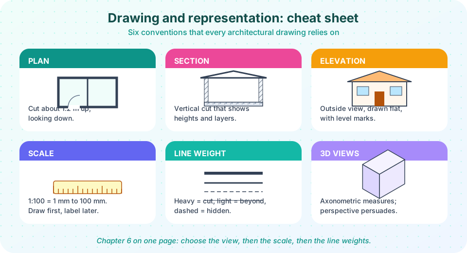
The chapter in one table
| Topic | Key idea | Rule to remember |
|---|---|---|
| Plan | Horizontal cut looking down | About 1.2 m above the floor; cut elements heavy |
| Section | Vertical cut | Shows heights and construction; name it A-A with arrows |
| Elevation | Flat view of one side | No perspective; level marks relative to +0.00 |
| Stairs | Comfort geometry | 2R + T = 600 to 650 mm; treads = risers - 1 |
| Scale | Ratio of paper to real | 1:100 means 1 cm = 1 m; larger scale = smaller ratio |
| Line weight | Hierarchy | Cut heavy, beyond medium, texture and dimensions fine |
| Dimensions | Written authority | Millimeters, no repeats, never scale from print |
| Paper | ISO A series | A1 594 x 841, A3 297 x 420, A4 210 x 297 mm |
| Axonometric | Parallel projection | Edges parallel, measurable; isometric axes at 30 degrees |
| Perspective | Converging lines | Horizon at eye height; one, two or three vanishing points |
| BIM | Model with data | Drawings generated from one model |
Where the pieces meet
- A section is what you cut from a plan; the arrows on the plan name the view, and level marks tie it to the elevation.
- Scale decides how much line weight is possible: a 0.5 mm line at 1:500 is already 250 mm thick in reality.
- An axonometric is often built from the plan, by raising walls up the vertical axis; a perspective is built from a plan and an eye position.
- Models and BIM do not replace drawings; they generate and check them.
A worked example that uses the whole chapter
Imagine you must draw a room 4.8 m by 3.6 m with a 900 mm door, at 1:50 on an A4 sheet. On paper the room is 4800 / 50 = 96 mm by 3600 / 50 = 72 mm, and the door is 18 mm wide, so the plan fits easily on A4 (210 x 297 mm) with room for a title block and a graphic scale. Now add a stair in section: floor-to-floor 2,700 mm, 15 risers of 180 mm and treads of 250 mm give 2R + T = 610 mm, within the comfortable band, and a flight length of 14 x 250 = 3,500 mm, which is 70 mm on the 1:50 sheet. Draw the cut line on the plan, letter the ends A, and make the cut elements heavy in the section. Finally, check that the ceiling height in the section matches the height written in the elevation. The exercise touches every convention in the chapter: scale, line weight, dimensions, section marks and coordination.
Try it
Flip through the chapter's flashcards. Click the card to reveal the answer.
Now check your arithmetic. Predict each result before running the code.
Press Run (or Ctrl + Enter) to see the result here.
Program input · what you'd type while the program runs
Type the answers before you press Run, one per line. Each time the program reads a line (with input()), it gets the next line from this box.
Check your understanding
Quick check · 10 questions
of 10 answered You scored / 10 · perfect!
-
1. On a 1:20 drawing a wall section measures 15 mm thick. How thick is the real wall?
15 mm x 20 = 300 mm. -
2. Which pair describes a plan and a section correctly?
A plan is a horizontal slice looking down; a section is a vertical slice. -
3. A drawing set shows the ridge at +3.70 in the section but +3.60 in an elevation. What is the problem?
All views must agree; a mismatch is an error that must be resolved before building. -
4. Why are dimensions written in numbers instead of scaled off the drawing?
Copying and printing change sizes. -
5. Which line type usually marks a centre line?
Dash-dot lines mark axes and centre lines. -
6. How is the horizon line related to the viewer's eye in a perspective?
The horizon line coincides with the eye level of the viewer. -
7. Floor-to-floor is 2,700 mm with 15 risers. What is the riser height?
2700 / 15 = 180 mm. -
8. What is the main advantage of an exploded axonometric?
Pulling layers apart makes the construction legible. -
9. Which sheet is bigger?
A1 is 594 x 841 mm; A3 is 297 x 420 mm; A4 is 210 x 297 mm. -
10. What does BIM add compared with simple 3D CAD?
BIM objects hold data, so views and schedules come from one model.
Summary
- Choose the view by the question: plan for layout, section for height and construction, elevation for appearance.
- Scale, line weight and dimensions make drawings readable and reliable.
- Axonometrics measure, perspectives persuade; models and BIM check and coordinate.
- Coordination across drawings is the core professional habit.
Next: Chapter 7 overview: sustainable and urban architecture
Track your progress
Create a free account to tick off lessons and pick up where you left off on any device.
of Introduction to Architecture lessons completed