


















Lesson 28 of 46 · Drawing and Representation
Plans, sections and elevations
Learn how a plan, a section and an elevation are cut and drawn, how they relate, and how to read stairs, doors, windows and level marks, with worked examples.
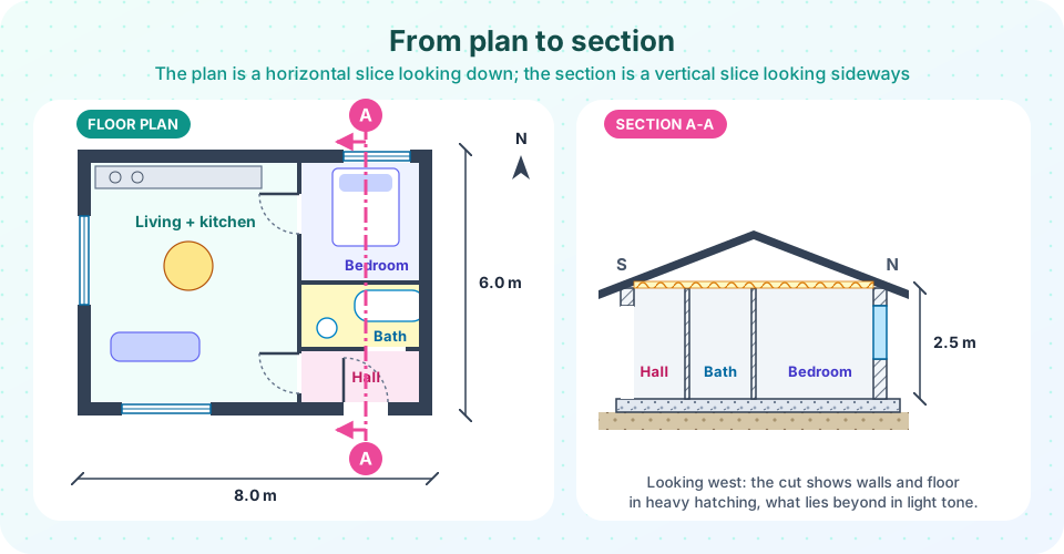
Imagine slicing a house with a giant knife. If you cut horizontally and look down at the lower half, you see a plan. If you cut vertically and look at the cut face, you see a section. If you do not cut at all, but stand back and look at the outside, you see an elevation. These three views, which architects call the orthographic set, are the backbone of every drawing package, from a garden shed to a hospital.
The difference between a beginner's drawing and a professional's is rarely artistic skill. It is that the professional knows exactly what each drawing is supposed to show, and what it is allowed to leave out.
What you will learn
- How a plan is cut and what its symbols mean
- How a section is cut, and what is drawn heavy and what is light
- How an elevation relates to plans and sections through levels and datums
- How stairs are designed with a simple formula and drawn on a plan
- How to read a set of three related drawings as one building
Key terms
Poche: the solid fill (black or hatched) of walls and other elements that are cut by the plane of a plan or section.
Cut line (section line): the line on a plan that shows where a section is taken and in which direction you look.
Datum: a fixed reference level, usually the finished ground-floor level, written +0.00; other heights are given relative to it.
Riser and tread: the vertical and horizontal parts of a step.
Orientation: which way the drawing is turned; plans usually carry a north arrow.
The plan
A plan is a horizontal section cut at about 1.2 meters above the floor (conventions vary slightly from country to country). Everything the plane cuts through, mainly walls, columns and the frames of doors and windows, is drawn heavy and often filled solid. Everything below the plane, such as floor patterns, furniture and the treads of stairs, is drawn light. Things above the cut plane that matter, such as a roof overhang or a high shelf, are drawn dashed.
Standard symbols make plans quick to read:
- Walls are two parallel lines with poche between them. Thick walls for the structure or the envelope, thin for partitions.
- Doors are a gap in the wall, a thin straight line for the open leaf, and a quarter-circle arc that shows how far the door swings. The arc tells the reader which side the door opens to, and the space needed for it.
- Windows are a gap in the wall with three thin lines (two for the frame, one for the glass) because the plan cuts through the window at about 1.2 m, where it is glazed.
- Stairs are a series of parallel lines, one per tread, with an arrow marked "up" starting at the lowest step. The staircase is shown cut with a diagonal break line, because the cut plane passes through the stair at about 1.2 m, and the part above is not drawn.
- Fixtures, such as baths, toilets, kitchen units and beds, give scale and meaning to a room.
A plan also needs a north arrow, room names, and a scale (see Scale, line weight and dimensions).
The section
A section is a vertical slice. Like a plan, it has a cut: heavy lines and poche for everything the plane passes through (walls, floors, the roof structure, the ground), and lighter lines for everything seen beyond the cut. This is the drawing that shows how the building is built and how tall it is: floor thickness, ceiling height, insulation layers, the slope of the roof, the depth of the foundations and the height of window sills and heads.
Sections are marked on plans by a cut line with arrows at the ends. The arrows point in the direction of view, and each end carries a letter (A, B, C) so that the section can be named "Section A-A". In the drawing above, the cut runs from south to north through the hall, the bath and the bedroom, looking west. That is why the south wall shows a door opening and the north wall shows a window.
Good sections are chosen deliberately. Architects cut through stairs, changes of level, double-height spaces, and places where the structure is complex, because that is where the building is hardest to understand. A section that cuts only through plain walls teaches the reader nothing.
The elevation
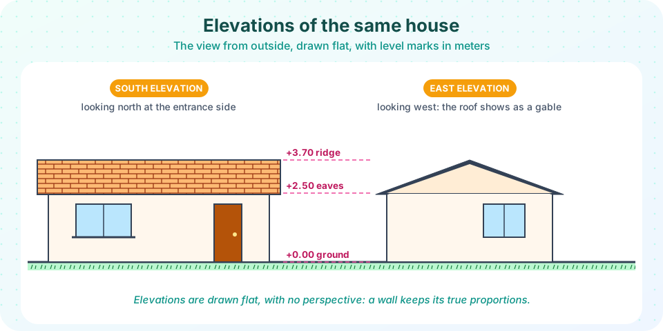
An elevation is a view of one side of a building, drawn as if every point were projected straight onto a vertical plane. There is no perspective: a window at the back of a recess is drawn at the same size as one at the front, and parallel lines stay parallel. Elevations are named by the direction they face (south elevation, north elevation) or, in some countries, by their position (front, rear, left, right).
They show the facade design: windows, doors, materials, roof shape, chimneys, and the heights of eaves and ridge, which are given on level marks relative to the datum (+0.00 ground floor, +2.50 eaves, +3.70 ridge). Elevations are the drawings that planning authorities study most closely, because they show what the neighborhood will see.
Making the three agree
The most important habit in drawing is coordination. The three views describe one building, so every dimension must agree:
- A window that is 1.2 m wide in the plan must be 1.2 m wide in the elevation.
- A sill height of 0.9 m in the section must show as 0.9 m above the ground floor in the elevation.
- The ridge at +3.70 in the section must be at +3.70 in every elevation.
Architects often draw the three on the same sheet, with the section and elevation projected straight from the plan using light construction lines. Good CAD and BIM software does this automatically, but you still need to know what to check.
Designing stairs
Stairs combine geometry with human comfort, and the rule of thumb is Blondel's formula:
2 x riser + tread = 600 to 650 mm
A riser of 175 mm and a tread of 260 mm gives 2 x 175 + 260 = 610 mm, a comfortable stair. To design one:
- Take the floor-to-floor height, for example 2,800 mm.
- Divide by a target riser height of about 175 mm:
2800 / 175 = 16risers exactly. - There is always one fewer tread than risers in a flight (the top floor is the last "tread"), so 16 risers need 15 treads.
- The horizontal length of the flight is
15 x 260 = 3,900 mm.
Each country has its own limits on maximum riser and minimum tread, so a real design follows the local code.
Common misconceptions
"A plan shows everything you would see from above." A plan is a slice at about 1.2 m, not a bird's-eye view: a roof is not shown in a floor plan at all, and a table below the cut plane is shown but a high shelf above it is dashed.
"Elevations show perspective." They are flat projections; things further away are not smaller.
"A section is a drawing of an inside wall." A section is a cut through the whole building, and it is drawn to show how it is made, not just what it looks like.
"Door arcs are decoration." They show clearance; furniture inside the arc would block the door.
Try it
First, a stair calculator that applies Blondel's formula. Change the floor-to-floor height or the target riser and see how the numbers move.
Press Run (or Ctrl + Enter) to see the result here.
Program input · what you'd type while the program runs
Type the answers before you press Run, one per line. Each time the program reads a line (with input()), it gets the next line from this box.
Second, a cut-line explorer. A plan has three rooms in a row (west to east: living room 5 m, kitchen 3 m, bedroom 4 m). Move the cut and see which rooms the section passes through. Notice how the section width changes with where you cut.
Check your understanding
Quick check · 5 questions
of 5 answered You scored / 5 · perfect!
-
1. At roughly what height is a plan conventionally cut?
About 1.2 m, so the cut passes through doors, windows and walls but not low furniture. -
2. A floor-to-floor height is 3,000 mm and you choose 15 risers. What is each riser?
3000 / 15 = 200 mm. -
3. What do the arrows at the ends of a section line show?
They show which way the observer looks when the section is drawn. -
4. A flight has 14 risers. How many treads does it have?
There is always one fewer tread than riser, because the upper floor acts as the last tread. -
5. Which statement about an elevation is true?
An elevation is orthographic, so windows keep their true size regardless of depth.
Summary
- A plan is a horizontal cut at about 1.2 m, a section is a vertical cut, an elevation is an uncut view of one side.
- Cut elements are drawn heavy, usually with poche; elements beyond are lighter.
- Section lines carry letters and arrows that show the viewing direction.
- Level marks relative to a datum link elevations and sections.
- Stairs follow
2R + T = 600 to 650 mmwith one fewer tread than risers. - Always check that dimensions agree across the three views.
Track your progress
Create a free account to tick off lessons and pick up where you left off on any device.
of Introduction to Architecture lessons completed