


















Lesson 29 of 46 · Drawing and Representation
Scale, line weight and dimensions
Choose the right scale, use line weights to guide the eye, write dimensions that builders can trust and read symbols, hatches and title blocks on drawing sheets.
A drawing is only useful if somebody else can read it. That "somebody" might be a builder at a muddy site with a rolled-up sheet in the wind, a planner with fifty applications to review, or you, six months later. Three conventions do most of the work of making a drawing readable: scale (how big things are), line weight (what matters most) and dimensions and annotations (exact numbers and names).
None of these conventions is difficult, but the details matter. A wrong scale ruins every measurement. A drawing in which every line has the same weight is a gray tangle. A dimension that appears twice, with two different values, can cost thousands to correct on site.
What you will learn
- How to read, choose and convert scales
- Which line types a drawing uses, and what each one means
- Rules for writing clear dimensions
- Common symbols, hatches and the parts of a title block
- Standard paper sizes and how to choose one
Key terms
Scale ratio: a ratio such as 1:50. One unit on the drawing represents that many units in the real building.
Graphic scale: a bar drawn on the sheet that shows real lengths and keeps its accuracy when a drawing is enlarged or reduced.
Line weight: the thickness of a line, used to rank what the reader should see first.
Dimension chain: a row of consecutive measurements along a wall.
Title block: the labeled panel on a sheet that gives project, drawing number, scale, date and revision.
Scale
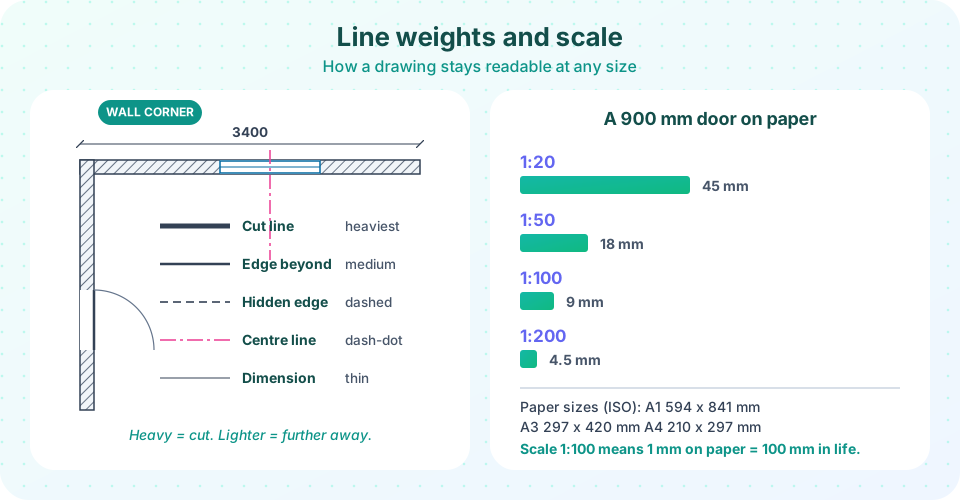
A scale of 1:100 means that 1 mm on the drawing stands for 100 mm in life, or, handier, 1 cm on paper is 1 m in the building. A wall that is 8 m long is 80 mm long on a 1:100 sheet. The ratio is always the same for every length on that drawing, so you can measure any part with a scale ruler.
Architects pick the scale according to what the drawing has to show:
| Scale | Typical use |
|---|---|
| 1:5000 to 1:500 | Maps and site plans |
| 1:200 | Urban blocks, large building plans |
| 1:100 | Floor plans, sections and elevations of houses, planning drawings |
| 1:50 | Detailed floor plans, interiors, small sections |
| 1:20 | Construction sections through walls and floors |
| 1:10, 1:5, 1:2, 1:1 | Details of joints, junctions and fittings |
A rough rule: the more information you have to show, the larger the scale (the smaller the second number). A planning drawing at 1:100 shows walls, doors and rooms. A drawing at 1:5 shows the layers of a wall, the thickness of a damp-proof membrane and the screws.
A graphic scale (a ruler drawn on the sheet) is added because drawings are often copied, reduced to A3 or sent as a PDF: the printed ratio might change, but the bar changes with it.
Worked example. On a 1:50 drawing, a corridor measures 52 mm between its walls. Real width = 52 x 50 = 2,600 mm = 2.6 m. A 900 mm door on the same drawing measures 900 / 50 = 18 mm.
Line weights
Imagine a plan where all lines are drawn with the same pen. Walls, furniture, dimension lines and door arcs would compete, and the eye could not find the building. Line weight solves this by giving a hierarchy:
- Heavy (about 0.5 to 0.7 mm): the cut. Walls and floors in plans and sections, ground lines in elevations.
- Medium (about 0.25 to 0.35 mm): edges of objects beyond the cut, window frames, door leaves, stair treads.
- Fine (about 0.13 to 0.18 mm): hatching, dimension lines, grid lines, furniture, textures.
Different line types carry meaning too: continuous for visible edges, dashed for hidden edges or things above the cut plane, dash-dot for centre lines and axes, and wavy or zig-zag for break lines that show a part has been omitted. A good test is to squint at a drawing: if the building looks like a clear silhouette, the line weights work.
Dimensions
A dimension is a promise from the architect to the builder, so the rules are strict:
- Metric drawings use millimeters and omit the unit; levels and site dimensions are often in meters. Write
2400, not2400 mmor2.4, unless the sheet says otherwise. - Use dimension lines with ticks or arrows at both ends, extension lines that start with a small gap from the object (about 1 to 2 mm) and run a little beyond the dimension line, and numbers written above the line.
- Read from the bottom and the right of the sheet: numbers on vertical dimension lines face right.
- Chains and totals: give the individual dimensions along a wall and the overall dimension on an outer line. Never repeat a dimension: if the total can be calculated, you may leave out one individual dimension of the chain so that errors cannot accumulate.
- Dimension to structure (the face of the wall, the centre line of a column) in a consistent way, and say which.
- Do not dimension to the paper. Never ask a builder to scale from a drawing; if a number is missing, the drawing is incomplete.
Dimensions are accompanied by annotations: room names and numbers, notes about materials ("200 mm reinforced concrete slab"), and references that point to larger-scale details ("see detail 4, sheet A-501").
Symbols and hatches
Drawing is a visual language with a limited vocabulary. Some frequently used symbols:
- North arrow, section marks (a line with arrowheads and a letter), level marks (a triangle with a height such as +2.50), grid bubbles (circles with numbers or letters that name structural grid lines), door and window tags (small circles or hexagons with a number that refers to a schedule).
- Hatches (fills) that show materials in section: concrete is shown with dots and small triangles, brick with diagonal lines, insulation with a wavy line, timber with parallel grain lines, earth with random specks. Standards differ between countries, and every drawing set includes a legend that explains which hatch means what.
Sheets and title blocks
Paper comes in ISO "A" sizes, each half the area of the one above: A0 is 841 x 1189 mm (1 m2), A1 is 594 x 841, A2 is 420 x 594, A3 is 297 x 420 and A4 is 210 x 297 mm. Every size has the same proportion (1 : the square root of 2), so a sheet can be reduced to the next size down without cropping. Large projects use A1 or A0 for plans, while A3 is common for reports and presentations.
Every sheet has a title block in a fixed corner or strip. It states the project name, drawing title, scale, date, the drawing number and revision letter, and who drew and checked it. A revision history tells builders whether they hold the latest drawing. In practice, "built from the wrong revision" is a classic site error, so title blocks are not decoration.
Common misconceptions
"1:50 is a smaller scale than 1:100." A larger scale means a smaller second number; 1:50 is larger than 1:100 because the building appears bigger on paper.
"If it is on the drawing, you can scale it with a ruler." Builders must use written dimensions. Printing and photocopying change sizes.
"All lines should be thin and neat." A drawing in uniform fine lines is hard to read; the hierarchy of weights is what gives it clarity.
Try it
First, a calculator that handles scale conversion and checks a dimension chain against its overall dimension. This is exactly what you do when you proof a drawing.
Press Run (or Ctrl + Enter) to see the result here.
Program input · what you'd type while the program runs
Type the answers before you press Run, one per line. Each time the program reads a line (with input()), it gets the next line from this box.
Second, a ruler that shows how long a real length is on paper. Choose a scale and a real length, and the bar's physical width on your screen (at 96 pixels per inch, which is about 3.78 pixels per millimeter) is drawn for you.
Check your understanding
Quick check · 5 questions
of 5 answered You scored / 5 · perfect!
-
1. On a 1:100 drawing, a wall measures 62 mm. How long is the real wall?
62 mm x 100 = 6,200 mm = 6.2 m. -
2. Which line weight should a cut wall have in a plan?
Cut elements get the heaviest line so that the reader sees the building's outline first. -
3. Which is the LARGER scale?
1:5 shows more detail because objects appear five times smaller than reality, not 100 or 200 times. -
4. What is a dash-dot line normally used for?
Dash-dot lines mark axes and centre lines; hidden edges use dashes. -
5. Why should a builder not scale dimensions from a printed drawing?
The written dimension is the contract; the paper size may have been altered by reduction or copying.
Summary
- Scale is a ratio: at 1:100, 1 cm on paper is 1 m in the building. Larger detail needs a larger scale (1:20, 1:5).
- Line weight ranks information: cut is heavy, beyond is medium, texture and dimension are fine.
- Dimensions use millimeters, avoid repetition and are the authority; never scale from a print.
- Symbols, hatches and title blocks make a drawing set a coordinated language.
- ISO A sizes halve in area at each step; A1 and A0 are for plans, A3 for reports.
Next: 3D views and models
Track your progress
Create a free account to tick off lessons and pick up where you left off on any device.
of Introduction to Architecture lessons completed