


















Lesson 27 of 45 · MOS Capacitors and MOSFETs
Chapter overview: MOS Capacitors and MOSFETs
A guide to the MOSFET chapter: how a gate voltage forms a channel, why this device dominates modern chips, and what each lesson in the chapter covers.
Every smartphone processor holds billions of one device: the metal-oxide-semiconductor field-effect transistor, or MOSFET. The idea is older than the bipolar transistor. Julius Lilienfeld patented a field-effect device in 1925, but nobody could make a clean enough semiconductor surface. Only in 1959 did Mohamed Atalla and Dawon Kahng at Bell Labs make a working silicon MOSFET, using the exceptionally good interface between silicon and its own oxide. That interface is the reason silicon, not germanium, runs the world.
What you will learn in this chapter
- How a MOS capacitor behaves as the gate voltage moves from accumulation through depletion to inversion.
- How the threshold voltage V_T is set by doping, oxide thickness and work functions.
- How the drain current of a MOSFET depends on V_GS and V_DS in the triode and saturation regions.
- What transconductance, output resistance and subthreshold slope mean for amplifiers and switches.
- How a pair of complementary MOSFETs forms the CMOS inverter, and why it uses almost no static power.
Key terms
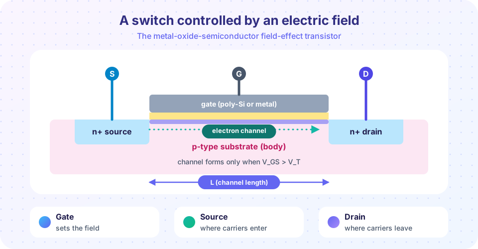
Gate: the electrode separated from the silicon by a thin oxide insulator.
Channel: the thin sheet of mobile carriers induced under the gate.
Threshold voltage (V_T): the gate voltage at which strong inversion begins.
Overdrive voltage (V_ov): V_GS − V_T, the amount by which the gate exceeds the threshold.
CMOS: complementary MOS, using both n-channel and p-channel transistors.
From capacitor to transistor
The core of a MOSFET is a MOS capacitor: gate metal (or heavily doped polysilicon), a thin oxide, and the silicon body. Apply a voltage to the gate and the electric field penetrates the oxide into the silicon, rearranging carriers near the surface. For a p-type body, a negative gate pulls holes to the surface (accumulation); a small positive gate pushes holes away (depletion); and a larger positive gate attracts electrons, creating an inversion layer that is n-type even though the body is p-type. Add an n+ source and an n+ drain at the two ends of that layer and you have a switch: no inversion, no path; inversion, a path.
The gate is insulated, so it draws no DC current. That means a MOSFET is controlled by voltage, not by current as a BJT is. Digital circuits made from MOSFETs can hold a state indefinitely with almost no power, which is why a chip with a billion transistors does not melt.
A capacitor with a secret
Three states
Drain current
CMOS
Why it won
Lessons in this chapter
- The MOS capacitor: the three states, band bending, depletion width, threshold and C-V curves.
- MOSFET operation: the current equations in triode and saturation, and channel-length modulation.
- Small signal, subthreshold and CMOS: g_m, r_o, the 60 mV/decade limit and the CMOS inverter.
- Chapter review: one picture, a recap table and a ten-question quiz.
Try it
Slide the gate voltage and watch the channel. The widget assumes V_T = 0.5 V and a simple square-law current; it is a demonstration, not a device simulator.
Check your understanding
Quick check · 3 questions
of 3 answered You scored / 3 · perfect!
-
1. What separates the gate of a MOSFET from the silicon?
The gate oxide (traditionally SiO₂) insulates the gate, so no DC current flows into it. -
2. In an n-channel MOSFET, the channel is formed by
A gate above V_T attracts electrons to the surface of the p-type body, creating an n-type layer. -
3. Why is CMOS attractive for large chips?
In a CMOS gate one of the two transistors is always off in a steady state, so there is no DC path from supply to ground.
Summary
- A MOSFET is a MOS capacitor plus a source and a drain; the gate field creates or removes a channel.
- Gate current is essentially zero in DC, so the device is controlled by voltage.
- Triode and saturation describe how the channel behaves as the drain voltage rises.
- CMOS pairs n-channel and p-channel devices to give logic with very low static power.
Next: The MOS capacitor
Track your progress
Create a free account to tick off lessons and pick up where you left off on any device.
of Semiconductor Devices lessons completed