


















Lesson 46 of 46 · Projects and Practice
Further Study: Where to Go After RF
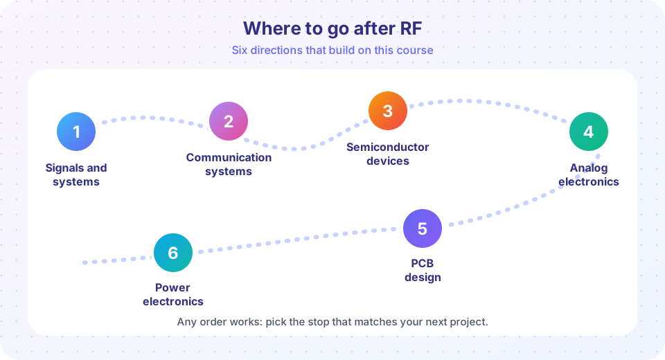
A roadmap from RF and antennas to signals and systems, communication systems, semiconductor devices, analog electronics, PCB design and power electronics.
You can now follow a signal from a transmitter, through an antenna, across space and through a receiver, and put numbers on every step. RF touches many fields, so there are many good directions. This page suggests six, with what each adds to your toolbox and how it connects to what you have done here.
What you will learn
- Which neighboring subjects strengthen your RF skills.
- What to practice with each.
The six stops
- Signals and systems: Fourier analysis, filtering and sampling. The language behind every spectrum plot and mixer product in this course.
- Communication systems: modulation, bandwidth, coding and bit-error rates. It turns the link budget's SNR into data rates and Eb/N0.
- Semiconductor devices: diodes, BJTs and FETs. Understand where noise figure, P1dB and IP3 come from inside the transistor.
- Analog electronics: biasing, feedback and op-amps, the base for RF amplifier and oscillator design.
- PCB design: controlled-impedance traces, grounding and layout. Your patch antenna and matching networks live on a board.
- Power electronics: switching converters and power amplifiers; efficiency and heat matter for every transmitter.
For the physics underneath, the track on electricity and magnetism covers Maxwell's equations, and waves and optics covers interference and diffraction, the same effects as Fresnel zones and arrays.
Skills worth practicing
- Build a small project: a 2.4 GHz patch or Yagi, a simple receiver, or a Wi-Fi link survey with a laptop.
- Learn a network analyzer workflow: measuring S11, calibrating and reading the Smith chart.
- Try an EM simulator on the patch of this course and compare it with the design equations.
- Read data sheets with a link budget in mind: check noise figure, P1dB, IIP3 and conversion loss.
Common misconceptions
"RF is a different world from circuits." It is the same laws at higher frequency, where lengths matter and wires become transmission lines.
"I must know everything before building." A simple measured project teaches more than a month of reading.
Try it
Press Run (or Ctrl + Enter) to see the console output here.
No output.
Press Run (or Ctrl + Enter) to see the console output here.
No output.
Check your understanding
Quick check · 3 questions
of 3 answered You scored / 3 · perfect!
-
1. Which subject best explains how a bit-error rate follows from the SNR of a link?
Modulation and detection theory link SNR or Eb/N0 to error rate. -
2. Where would you learn how to route a 50 ohm trace?
Controlled impedance routing is a PCB design topic. -
3. Fresnel zones and array patterns are both examples of
Both come from adding waves with different path lengths.
Summary
- Signals, communications, devices, analog, PCB and power are the six natural next steps.
- Build and measure something; the equations make more sense once you have.
Back to the course overview.
Track your progress
Create a free account to tick off lessons and pick up where you left off on any device.
of RF Engineering and Antennas lessons completed