


















Lesson 34 of 46 · Antenna Types and Arrays
Arrays and Beamforming
Learn the array factor of a uniform linear array, how phase steers the beam, why spacing creates grating lobes, how tapering lowers sidelobes, and how beamforming works.
One antenna has a fixed pattern. Several antennas fed together have a pattern you can design, and if you control the phase of each feed, a pattern you can change in microseconds with no moving parts. That is the idea behind radar arrays, 5G base stations and the antennas on low-orbit satellites. The mathematics is simple: add the fields from each element with the right phase delays. This lesson develops the array factor, steering, grating lobes, tapering and a short overview of how beamforming is implemented.
What you will learn
- How to write and evaluate the array factor of a uniform linear array.
- How progressive phase steers the beam, and how beamwidth changes with scan angle.
- Why element spacing above about half a wavelength creates grating lobes.
- How amplitude tapering trades sidelobe level for beamwidth.
Key terms
Array factor (AF): the pattern of the array if every element were an isotropic point source. Pattern multiplication: total pattern = element pattern x array factor. Progressive phase β: the constant phase difference between adjacent elements. Grating lobe: an extra full-strength main beam that appears when elements are spaced too far apart. Taper (window): weighting the element amplitudes to lower sidelobes.
The array factor
Place N identical elements on a line, spaced d apart, with angle θ measured from the broadside direction (perpendicular to the line). A far-field point sees element n delayed by n k d sin θ, with k = 2π/λ. If element n is also fed with phase n β, the fields add as
AF(θ) = Σ_{n=0}^{N-1} e^{j n ψ}, ψ = k d sin θ + β
which sums to
|AF| = |sin(N ψ/2) / sin(ψ/2)|, normalized: |AF|/N
The maximum occurs when ψ = 0, so the main beam points where k d sin θ0 + β = 0, that is
β = - k d sin θ0 = - 2π (d/λ) sin θ0
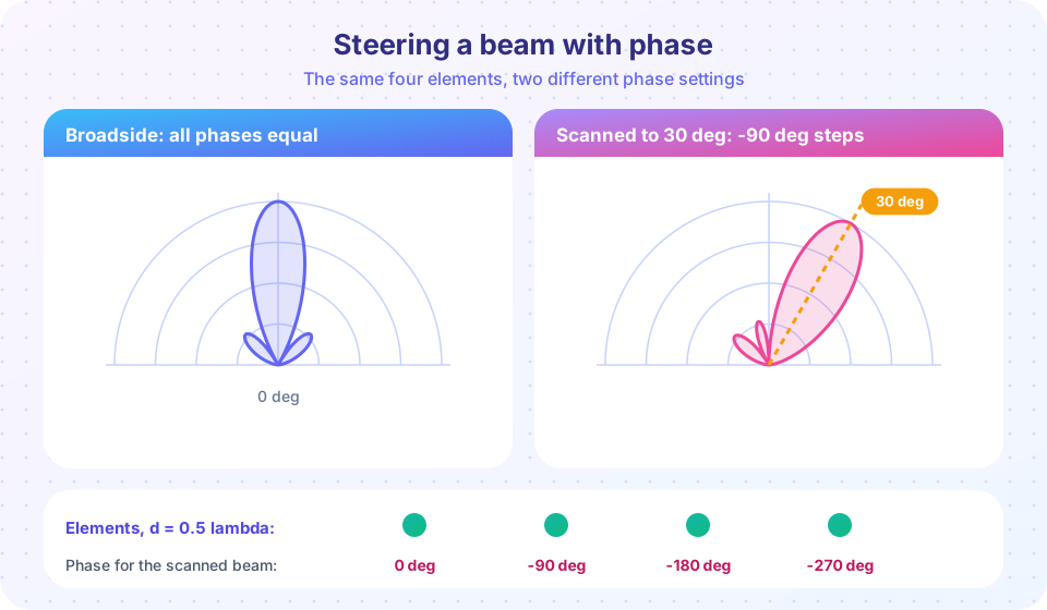
For d = λ/2 and θ0 = 30°: β = -π/2 = -90°, which is exactly the setting in the figure: element phases 0, -90, -180 and -270 degrees.
Useful facts for uniform amplitudes:
- Nulls occur where
N ψ/2 = m π(m not a multiple of N). - Broadside HPBW
≈ 0.886 λ / (N d)radians; for N = 8, d = λ/2 that is 12.7 degrees. - First sidelobe is about -13.3 dB for large N.
- With
d = λ/2, the directivity of a broadside array of isotropic elements isD ≈ N. - When scanned to θ0, the beam widens by
1/cos θ0and the projected aperture shrinks, so gain falls roughly ascos θ0.
Pattern multiplication
If every element has the same pattern E_e(θ), the array pattern is E_e(θ) · AF(θ). The element pattern is broad and mild; the array factor is sharp. The product is sharp where both are large. In a patch array the patch pattern falls toward the horizon, so the array automatically has little radiation at very wide angles, which also lowers scan gain at the edges.
Spacing and grating lobes
The array factor repeats every time ψ changes by 2π. If the spacing is too large, a second solution of ψ = ±2π falls in real space (|sin θ| ≤ 1) and a grating lobe appears. To avoid it at every scan angle up to θ0:
d / λ < 1 / (1 + |sin θ0|)
For full scan to 90 degrees that means d < λ/2; for a scan limited to 30 degrees, d < 0.667 λ. But spacing much smaller than λ/2 increases mutual coupling and wastes elements, so λ/2 is the usual choice.
Tapering
Uniform illumination gives the narrowest beam for a given length but a -13 dB sidelobe. Weighting the center elements more than the edge ones lowers sidelobes at the price of a wider main lobe and lower efficiency. A Hamming window gives about -40 dB sidelobes, a Taylor or Dolph-Chebyshev taper lets you set a sidelobe level (for example, -30 dB) for the smallest possible beam broadening. Radar and communications standards often require low sidelobes to avoid interference, so tapering is common.
Beamforming in practice
- Analog (phase-shifter) beamforming: one RF chain, one phase shifter per element. Cheap and fast, one beam at a time.
- True time delay: delay lines replace phase shifters so the beam does not squint with frequency in wideband arrays.
- Digital beamforming: every element has its own receiver and ADC, so the processor can form many simultaneous beams and null interferers.
- Hybrid: subarrays that combine analog and digital, common at millimeter waves.
- MIMO: multiple antennas at both ends use the spatial dimension to carry several data streams, not just a single steered beam.
Common misconceptions
"More elements mean more power." They add gain by focusing power; the transmitter power sets the total. The array gain is also lost if element amplitudes or phases are not calibrated.
"A phased array can scan to ±90 degrees with full gain." Gain falls with cos θ0 and element patterns fall off, so practical scan is limited to about ±60 degrees.
"Grating lobes are sidelobes." They are as strong as the main lobe.
Try it
Press Run (or Ctrl + Enter) to see the result here.
Program input · what you'd type while the program runs
Type the answers before you press Run, one per line. Each time the program reads a line (with input()), it gets the next line from this box.
Press Run (or Ctrl + Enter) to see the result here.
Program input · what you'd type while the program runs
Type the answers before you press Run, one per line. Each time the program reads a line (with input()), it gets the next line from this box.
Press Run (or Ctrl + Enter) to see the console output here.
No output.
Check your understanding
Quick check · 5 questions
of 5 answered You scored / 5 · perfect!
-
1. Four elements, spacing 0.5 lambda. What progressive phase steers the beam to 30 degrees?
beta = -360 (0.5) sin 30 = -90 degrees per element. -
2. Which spacing guarantees no grating lobes at any scan angle?
d < lambda/(1 + |sin theta0|) is at most lambda/2 for full scan. -
3. Tapering the amplitudes of a uniform array will
That is the classical trade-off. -
4. The beam of an array scanned to 60 degrees is about this much wider than at broadside
Beamwidth scales as 1/cos(theta0): 2x at 60 degrees. -
5. An 8 element broadside array with d = lambda/2 of isotropic elements has directivity close to
D is about N for half-wave spacing.
Summary
AF = sin(Nψ/2) / (N sin(ψ/2)), withψ = kd sin θ + β; the beam points whereψ = 0.- Steering needs
β = -kd sin θ0; keepd < λ/(1 + |sin θ0|)to avoid grating lobes. - Pattern multiplication: element pattern times array factor.
- Tapering lowers sidelobes at the price of beamwidth; scanning widens the beam by
1/cos θ0.
Next: Chapter review
Track your progress
Create a free account to tick off lessons and pick up where you left off on any device.
of RF Engineering and Antennas lessons completed