


















Lesson 42 of 46 · Projects and Practice
Project: Design a 2.45 GHz Patch Antenna
Design a rectangular microstrip patch for 2.45 GHz on FR-4: width, effective permittivity, length, inset feed and a model of its return loss and bandwidth, step by step.
In this project you take a frequency and a board material and finish with a copper rectangle you could etch. You will compute the patch dimensions from the design equations, estimate the feed position, and build a simple resonator model to see how the bandwidth and the return loss behave. The result is a starting design; every real patch is tuned in a simulator or on a network analyzer, because the equations ignore many effects.
What you will learn
- How to apply the patch design equations in order.
- How to place an inset feed for a 50 ohm match.
- How to model the patch as a resonator and read bandwidth from it.
- Which design changes widen or shift the resonance.
Key terms
Inset feed: a microstrip line inserted into a notch of the patch at depth y0 from the radiating edge.
Edge resistance Redge: input resistance when fed at the edge of the radiating side.
Return loss: -20 log10 |Γ|; larger is better matched.
Loss tangent: tan δ, the fraction of stored energy lost per cycle in the substrate.
Specification
- Center frequency 2.45 GHz.
- Substrate FR-4:
εr = 4.4,h = 1.6 mm, copper 35 μm. (FR-4 is lossy at GHz:tan δis about 0.02, so expect low radiation efficiency. A low-loss laminate is better for real products.) - Feed: 50 ohm microstrip.
Step 1: Width
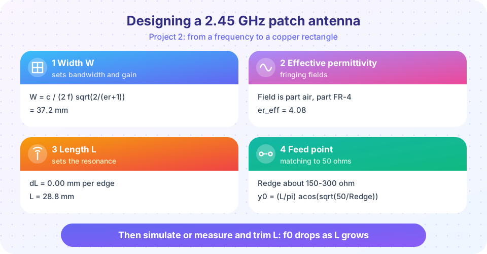
W = c / (2 f) · sqrt(2/(εr + 1)) = 0.0612 × 0.6086 = 37.2 mm
A wider patch lowers the edge resistance and raises the bandwidth a little, but must stay under about one wavelength in the dielectric to avoid higher modes.
Step 2: Effective permittivity
εeff = 2.7 + 1.7 × (1 + 12 × 1.6/37.2)^(-1/2) = 4.08
Part of the field lies in air, so the wave sees a value between 1 and 4.4.
Step 3: Length
The patch looks longer than its copper because of fringing, by ΔL = 0.74 mm at each radiating edge:
L = c / (2 f sqrt(εeff)) - 2 ΔL = 30.3 mm - 1.5 mm = 28.8 mm
A 1 mm error in L moves the resonance by about 78 MHz (lesson on wire and patch antennas), more than 3 percent of the frequency, which is why trimming the length is the standard tuning method.
Step 4: Feed point
The input resistance falls from Redge at the edge to zero at the center, following Rin(y0) = Redge cos²(π y0 / L). For Redge = 250 Ω (typical values are 150 to 300 Ω, from a simulator), the 50 ohm point is
y0 = (L/π) arccos(sqrt(50/250)) = 0.35 L, about 10 mm from the edge
An inset feed makes the notch carry the microstrip line to that depth, with small gaps on each side. The gap width is another tuning knob.
Step 5: Expected performance
A patch of this kind typically gives 5 to 7 dBi of gain, a bandwidth for VSWR 2:1 of about 1 to 3 percent of the center frequency (25 to 75 MHz; the 2.4 GHz Wi-Fi band is 83 MHz wide, so a plain FR-4 patch is marginal), a linear polarization along L, and an E-plane beamwidth near 70 to 80 degrees. For more bandwidth: a thicker or lower-permittivity substrate, an air gap, slots, or a stacked parasitic patch. For circular polarization: cut two opposite corners or feed at a diagonal.
Common misconceptions
"The equations give the final dimensions." They give a start. Ground plane size, feed, substrate tolerance and nearby parts all shift the frequency.
"A bigger ground plane never hurts." An infinite ground is assumed; practical sizes of about one wavelength per side are enough, and edges affect the pattern.
"Higher permittivity is better because it makes the patch smaller." It also reduces bandwidth and efficiency.
Try it
Press Run (or Ctrl + Enter) to see the result here.
Program input · what you'd type while the program runs
Type the answers before you press Run, one per line. Each time the program reads a line (with input()), it gets the next line from this box.
Press Run (or Ctrl + Enter) to see the result here.
Program input · what you'd type while the program runs
Type the answers before you press Run, one per line. Each time the program reads a line (with input()), it gets the next line from this box.
Press Run (or Ctrl + Enter) to see the console output here.
No output.
Check your understanding
Quick check · 4 questions
of 4 answered You scored / 4 · perfect!
-
1. To lower the resonant frequency of a finished patch you should
Resonance is at about half a guided wavelength; longer L, lower frequency. -
2. The inset feed is used to
Rin falls from the edge value toward the center. -
3. Bandwidth of a patch increases with
That lowers Q. -
4. FR-4 at 2.45 GHz mainly costs you
Loss tangent about 0.02 turns a lot of power into heat.
Summary
- Compute
W,εeff,ΔLandLin order, then choose the feed depth fromRin(y0) = Redge cos²(πy0/L). - Tune by length: 1 mm is about 78 MHz at this design.
- Widen the band with thicker, lower-permittivity substrates or stacked patches.
Track your progress
Create a free account to tick off lessons and pick up where you left off on any device.
of RF Engineering and Antennas lessons completed