


















Lesson 6 of 46 · Waves and Transmission Lines
Chapter 2 Overview: Waves on Cables and Transmission Lines
A map of chapter 2: why a cable needs wave theory once it is long compared with the wavelength, and what you will learn about Z0, reflections, VSWR and impedance transformation.
When you flip a switch on a short wire, the whole wire seems to change voltage at once. It does not: the change travels along the wire at a large fraction of the speed of light, taking about 5 ns per meter in a typical cable. For slow signals that delay is invisible. For radio signals it is the whole story, because the voltage at one end of a cable may be rising while the other end is falling.
Chapter 2 builds the theory of that traveling wave. It is the foundation for the Smith chart, matching networks, S-parameters, amplifiers and antennas that follow.
What you will learn
- Why long conductors must be modeled as distributed circuits with a characteristic impedance.
- How reflections form at a mismatched load and how to measure them with the reflection coefficient and VSWR.
- How impedance changes along a line, and how stubs and quarter-wave sections use that.
- How the same ideas apply to coax, microstrip, stripline and twin-lead.
The big idea
Everything else follows from these three facts.
The tools
You will use them for matching.
Where it is used
The same math, many uses.
The big picture
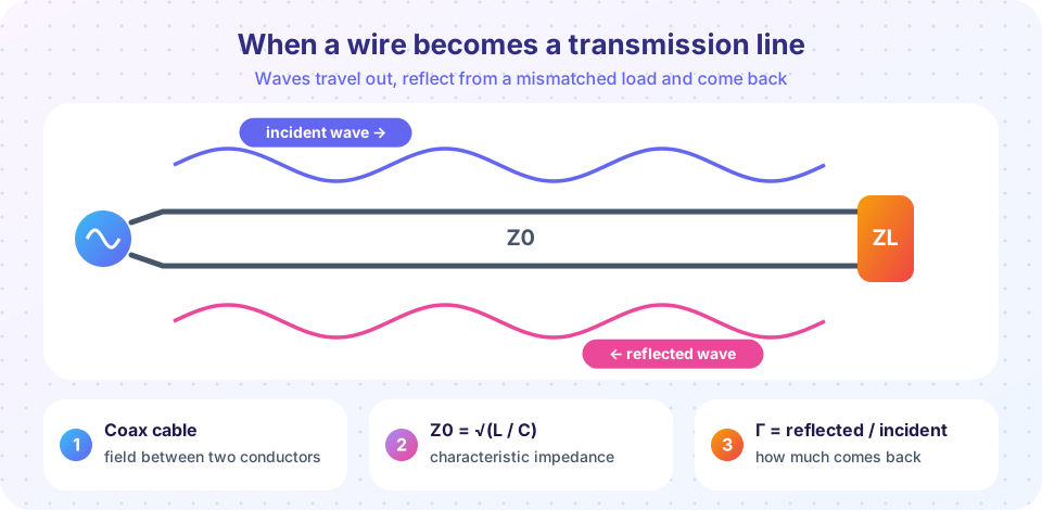
Imagine pushing a rope tied to a wall. A pulse runs along the rope, hits the wall and returns. A transmission line works the same way. A signal injected at one end travels as a wave of voltage and current, and what happens when it arrives depends on what it meets.
- If the load absorbs the wave completely, nothing comes back. The load is matched.
- If the load is an open circuit, the wave bounces back with the same polarity. A short circuit bounces it back inverted.
- Anything in between returns part of the wave, which then interferes with the forward wave and makes a standing wave pattern on the line.
The key number is the characteristic impedance Z0. It is not a resistance you can measure with an ohmmeter. It is the ratio of voltage to current for a wave traveling in one direction, and it depends only on the geometry and materials of the line: Z0 = √(L/C) in terms of inductance and capacitance per meter.
What each lesson covers
- The transmission line model: the ladder of tiny inductors and capacitors,
Z0, velocity and the coax formula. - Reflection coefficient and VSWR: how mismatch creates a standing wave, and return loss and mismatch loss.
- Impedance along a line: the input impedance formula, stubs and the quarter-wave transformer.
- Chapter 2 review: a one-page summary and ten questions.
Try it
This simulation sends a voltage step down a 50 Ω line and tracks the voltage at the load as the pulse bounces back and forth. The source resistance is 10 Ω and the load 150 Ω, so reflections occur at both ends and the load voltage rings up to its steady value, like a ball bouncing to rest.
Press Run (or Ctrl + Enter) to see the result here.
Program input · what you'd type while the program runs
Type the answers before you press Run, one per line. Each time the program reads a line (with input()), it gets the next line from this box.
The second tool shows why long lines are a problem for fast signals: it checks the same rule λ/10 for a cable at several frequencies and plots the phase shift along the cable.
Press Run (or Ctrl + Enter) to see the result here.
Program input · what you'd type while the program runs
Type the answers before you press Run, one per line. Each time the program reads a line (with input()), it gets the next line from this box.
Check your understanding
Quick check · 4 questions
of 4 answered You scored / 4 · perfect!
-
1. What does the characteristic impedance Z0 of a line represent?
Z0 relates the forward-wave voltage and current; it is set by geometry and materials, not by what is connected. -
2. A transmission line is terminated in an open circuit. The reflected wave has
An open circuit reflects the voltage wave with Γ = +1. -
3. Why do we need transmission-line theory above about λ/10?
At λ/10 and beyond, the phase change along the conductor can no longer be ignored. -
4. A line is matched when
A load equal to Z0 absorbs the whole wave.
Summary
- Signals take time to travel; at RF that delay matters.
- A transmission line has a characteristic impedance
Z0 = √(L/C)and carries forward and reflected waves. - A mismatched load reflects part of the wave, creating a standing wave.
- Chapter 2 covers the line model, reflection and VSWR, impedance transformation and stubs.
Track your progress
Create a free account to tick off lessons and pick up where you left off on any device.
of RF Engineering and Antennas lessons completed