


















Lesson 7 of 46 · Waves and Transmission Lines
The Transmission Line Model: Z0, Velocity and Loss
Build the transmission line from tiny R, L, G and C elements, derive Z0 and velocity, and compute coax impedance from its dimensions with a live calculator.
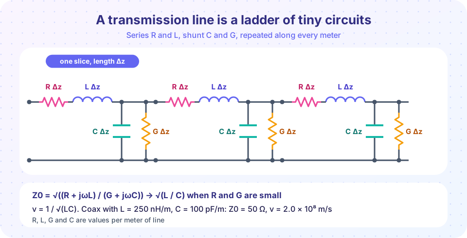
A transmission line is any pair of conductors long enough that you must think of signals as waves: coax, twin-lead, a microstrip trace on a circuit board, even two parallel wires in a power cord. The trick for understanding every one of them is the same. Cut the line into very short slices. Each slice is so short that ordinary circuit theory works inside it, and each slice contains the same four elements. Chain the slices together, take the limit of infinitely many tiny slices, and the wave behavior falls out.
What you will learn
- The four per-meter parameters R, L, G and C and what physical effect each represents.
- The telegrapher's equations and the traveling-wave solution.
- How
Z0, phase velocity, wavelength and attenuation follow from RLGC. - How to compute the characteristic impedance of a coax from its dimensions.
- The main line types and when each is used.
Key terms
- Characteristic impedance (Z0): voltage-to-current ratio of a single traveling wave on the line.
- Propagation constant (γ = α + jβ): α is attenuation in nepers per meter; β is phase shift in radians per meter.
- Phase velocity (v): the speed at which a constant-phase point travels:
v = ω/β. - Velocity factor:
v / c, equal to1/√εrfor a line filled with a uniform dielectric. - Electrical length:
βl, the phase delay of a line section, in radians or degrees.
The four parameters
Looking at a short length Δz of a two-conductor line:
- R (Ω/m): series resistance of the two conductors. It makes the line lossy.
- L (H/m): series inductance from the magnetic field around the current. A larger loop means more inductance.
- C (F/m): shunt capacitance between the conductors. Closer conductors mean larger capacitance.
- G (S/m): shunt conductance, the leakage through an imperfect dielectric.
A slice has series impedance (R + jωL) Δz and shunt admittance (G + jωC) Δz.
The telegrapher's equations
Apply Kirchhoff's laws to one slice and let Δz → 0:
dV/dz = −(R + jωL) I
dI/dz = −(G + jωC) V
Differentiate and substitute to get a wave equation. The solution is a pair of waves:
V(z) = V⁺ e^(−γz) + V⁻ e^(+γz)
The first term travels toward +z (toward the load) and the second toward −z (reflected). The propagation constant and characteristic impedance are
γ = α + jβ = √((R + jωL)(G + jωC))
Z0 = √((R + jωL) / (G + jωC))
The lossless line: the case you use most
For good conductors and dielectrics at RF, R ≪ ωL and G ≪ ωC, so you can set both to zero:
Z0 = √(L / C)is a real number (a resistance, in ohms).β = ω √(L C).- Phase velocity
v = 1 / √(L C). - Wavelength
λ = 2π / β = v / f.
Worked example (the numbers in the picture). A coax has L = 250 nH/m and C = 100 pF/m.
Z0 = √(250×10⁻⁹ / 100×10⁻¹²) = √2500 = 50 Ω.v = 1 / √(250×10⁻⁹ × 100×10⁻¹²) = 1 / √(2.5×10⁻¹⁷) = 2.0×10⁸ m/s, a velocity factor of 0.667.- At 1 GHz,
λ = v / f = 0.2 m, so one meter of this cable is 5 wavelengths, a phase delay of 1800°. - Signal delay per meter is
1/v = 5 ns/m.
Notice that Z0 does not depend on length. A 1 cm piece and a 100 m reel of the same cable both have Z0 = 50 Ω.
Loss
With small R and G, the attenuation constant is approximately
α ≈ R/(2 Z0) + G Z0/2 nepers per meter
and 1 neper is 8.686 dB. The first term is conductor loss, which grows with frequency because current crowds into a thin layer near the surface (skin effect). The second is dielectric loss. Cable catalogs list attenuation in dB per 100 m at several frequencies; a thin RG-58-type cable loses on the order of 15 dB per 100 m at 100 MHz, while a large low-loss cable loses several times less. Use the manufacturer's figures for real designs.
Coax impedance from its dimensions
For a coax with outer-conductor inner diameter D, inner-conductor diameter d and dielectric constant εr:
Z0 = (60 / √εr) · ln(D / d) Ω
(the exact coefficient is η₀ / 2π ≈ 59.96).
Worked example. Solid polyethylene has εr ≈ 2.25. For Z0 = 50 Ω, ln(D/d) = 50 × 1.5 / 60 = 1.25, so D/d = 3.49. A 0.9 mm center conductor needs an insulator about 3.1 mm across. That is close to real RG-58 geometry.
The velocity factor is 1/√εr = 0.667. Foam dielectrics (εr ≈ 1.5) give factors near 0.82.
The main line types
- Coaxial cable: shielded, uniform, good to many GHz; the standard for cables and connectors.
- Microstrip: a trace over a ground plane on a circuit board. The field is partly in air and partly in the board, so the effective permittivity
εeffsits between 1 andεr. - Stripline: a trace buried between two ground planes; better isolation, simple
√εrbehavior. - Coplanar waveguide: a trace with ground on both sides in the same plane; common in MMICs.
- Twin-lead and parallel wire: classic 300 Ω TV cable; low loss but picks up interference.
- Waveguide: a hollow metal tube used above about 3 GHz for high power or low loss; it has a cutoff frequency and is not a two-conductor line.
Common misconceptions
- "Z0 is the resistance of the cable." An ohmmeter reads the DC resistance of the wire, a few ohms per 100 m.
Z0is a wave property set by geometry and dielectric. - "A longer cable has a higher Z0." Z0 is independent of length; length only sets delay and loss.
- "A 75 Ω cable can substitute for 50 Ω." The line will carry the signal, but the mismatch causes reflections. Systems are built around one
Z0, typically 50 Ω for RF and 75 Ω for video and cable TV.
Try it
First, a coax calculator. Choose the dielectric and the inner and outer diameters and see Z0, velocity factor and delay. Try to hit exactly 50 Ω.
Second, a numerical check of the formulas. The program computes Z0 and γ from RLGC at several frequencies, shows how a small R and G change the lossless result and plots attenuation against frequency.
Press Run (or Ctrl + Enter) to see the result here.
Program input · what you'd type while the program runs
Type the answers before you press Run, one per line. Each time the program reads a line (with input()), it gets the next line from this box.
Check your understanding
Quick check · 5 questions
of 5 answered You scored / 5 · perfect!
-
1. A lossless line has L = 400 nH/m and C = 100 pF/m. What is Z0?
Z0 = √(400×10⁻⁹ / 100×10⁻¹²) = √4000 = 63.2 Ω. -
2. A cable's dielectric has εr = 4. What is its velocity factor?
VF = 1/√εr = 1/2 = 0.5. -
3. Which statement about Z0 is true for a lossless line?
For the lossless line Z0 = √(L/C), a real constant. -
4. A 50 Ω coax (VF 0.667) is 2 m long. What is the delay?
Delay = length / v = 2 / (2×10⁸) = 10 ns. -
5. Why does conductor loss in a cable increase with frequency?
At higher frequency current flows in a thinner skin, raising the effective R.
Summary
- A transmission line is a chain of short slices with R, L, G and C per meter.
Z0 = √((R + jωL)/(G + jωC)); for low lossZ0 = √(L/C),v = 1/√(LC),β = ω√(LC).- Attenuation comes from conductors (R) and dielectric (G) and grows with frequency.
- Coax:
Z0 = (60/√εr) ln(D/d). - Z0 depends on geometry and materials only, never on length.
Track your progress
Create a free account to tick off lessons and pick up where you left off on any device.
of RF Engineering and Antennas lessons completed