


















Lesson 18 of 46 · S-Parameters and Microwave Networks
ABCD Matrices and Cascaded Networks
Learn to describe series, shunt and line sections with ABCD matrices, cascade them by multiplication, convert to S-parameters and analyze a lowpass filter.
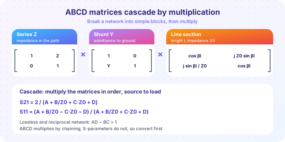
Real RF circuits are chains: a connector, a matching network, a transistor, a filter, a cable. S-parameters describe each block well, but they are awkward to combine: you cannot just multiply the S-matrices of two blocks to get the S-matrix of the chain. A different description is made for chaining: the ABCD matrix. Multiply the matrices of the blocks in order and you have the matrix of the whole chain. Then a short formula converts the result to S-parameters for a 50 Ω system.
What you will learn
- The definition of the ABCD matrix and the matrices of the basic blocks.
- How to cascade blocks by multiplying matrices in order.
- How to convert an ABCD matrix to S11 and S21 in a
Z0system. - How to analyze a lowpass filter built from capacitors and an inductor.
Key terms
- ABCD matrix: a 2×2 matrix relating input voltage and current to output voltage and current.
- Cascade: several two-ports connected output to input.
- Series element: an impedance
Zin the signal path. - Shunt element: an admittance
Yfrom the signal path to ground. - Cutoff frequency: the frequency where a lowpass filter's transmission has fallen by 3 dB.
Definition
For a two-port with input voltage V1 and current I1 (into the port) and output voltage V2 and current I2 (flowing out of port 2 into the load):
V1 = A V2 + B I2
I1 = C V2 + D I2
Written as a matrix, [V1; I1] = [A B; C D] [V2; I2]. The units are A, D dimensionless, B in ohms and C in siemens. Because the output current is defined as leaving the network, the output of one block is exactly the input of the next, and the matrices multiply in the order the blocks appear.
The building blocks
| Block | A | B | C | D |
|---|---|---|---|---|
Series impedance Z |
1 | Z |
0 | 1 |
Shunt admittance Y |
1 | 0 | Y |
1 |
Line (impedance Z0', length θ) |
cos θ |
jZ0' sin θ |
j sin θ / Z0' |
cos θ |
Ideal transformer (ratio n:1) |
n |
0 | 0 | 1/n |
Impedance values for components at angular frequency ω:
- Resistor:
Z = R,Y = 1/R. - Inductor:
Z = jωL,Y = 1/(jωL). - Capacitor:
Z = 1/(jωC),Y = jωC.
Two properties help catch mistakes: a reciprocal network has AD − BC = 1, and a lossless symmetrical network has A = D.
Cascading
If network 1 has matrix M1 and network 2 has M2, the cascade is M = M1 · M2. Matrix multiplication is not commutative, so the order matters: put the matrix for the block nearest the source on the left.
Worked example. A series 10 Ω resistor followed by a shunt 0.02 S conductance (50 Ω resistor):
[1 10; 0 1] · [1 0; 0.02 1] = [1 + 0.2, 10; 0.02, 1] = [1.2 10; 0.02 1]
Converting to S-parameters
For a system with reference impedance Z0 at both ports, let Δ = A + B/Z0 + C Z0 + D. Then
S11 = (A + B/Z0 − C Z0 − D) / Δ
S21 = 2 / Δ
S12 = 2 (AD − BC) / Δ
S22 = (−A + B/Z0 − C Z0 + D) / Δ
Check with the series 50 Ω resistor: A = D = 1, B = 50, C = 0, Δ = 1 + 1 + 1 = 3: S21 = 2/3 and S11 = (1 + 1 − 0 − 1)/3 = 1/3 ✓.
Example: a third-order lowpass filter
A Butterworth lowpass filter with 3 dB cutoff fc = 1 GHz in a 50 Ω system can be built as shunt C, series L, shunt C (a "pi" filter) with
C1 = C3 = 1 / (Z0 ωc) = 3.183 pF, L2 = 2 Z0 / ωc = 15.92 nH
(the element values 1, 2, 1 come from the Butterworth prototype table). The cascade is M = M_Y1 · M_Z · M_Y3 with Y1 = Y3 = jωC and Z = jωL. At ω = ωc the formulas give |S21| = −3.01 dB, exactly as designed. At twice the cutoff frequency the Butterworth response |S21|² = 1/(1 + (f/fc)⁶) = 1/65 gives an attenuation of 18.1 dB: the filter rolls off at 18 dB per octave, or 60 dB per decade (3 poles × 20 dB).
Notice how simple the method is: three small matrices and two multiplications turn a circuit diagram into frequency responses for S21 and S11.
When to use S-parameters and when to use ABCD
- Use ABCD to combine passive blocks you can describe with formulas: lumped elements, lines, transformers.
- Use S-parameters for measured or simulated components with arbitrary behavior, especially active ones.
- Convert between them freely. For a cascade of measured parts, convert to ABCD (or "T-parameters" for the same purpose with waves), multiply and convert back.
Common misconceptions
- "I can multiply S-matrices to cascade." The S-parameters of a cascade are not the product of the S-matrices. Only transfer-type matrices (ABCD, T) multiply.
- "The order of multiplication does not matter." Matrix multiplication is not commutative. Reversing the order gives the response of a different circuit.
- "I2 flows into port 2." In the ABCD convention
I2leaves the network. A wrong sign shifts a sign of B and C and produces nonsense.
Try it
This simulation builds the pi filter by multiplying matrices, converts to S-parameters, plots S21 and S11 and verifies the properties promised above.
Press Run (or Ctrl + Enter) to see the result here.
Program input · what you'd type while the program runs
Type the answers before you press Run, one per line. Each time the program reads a line (with input()), it gets the next line from this box.
Now build your own chain. Choose up to three blocks, set their values and the frequency, and read S11 and S21 of the cascade. The default is the Butterworth filter from above; change one block and see what happens to the response.
Check your understanding
Quick check · 5 questions
of 5 answered You scored / 5 · perfect!
-
1. What is the ABCD matrix of a series impedance Z?
A series element has B = Z and A = D = 1, C = 0. -
2. How do you combine two cascaded two-ports in ABCD form?
ABCD matrices cascade by multiplication, and the order follows the signal path. -
3. A series 50 Ω resistor in a 50 Ω system has Δ = A + B/Z0 + C·Z0 + D equal to
1 + 50/50 + 0 + 1 = 3, so S21 = 2/3. -
4. A 3rd-order Butterworth lowpass filter attenuates by about how much at twice its cutoff frequency?
|S21|² = 1/(1 + 2⁶) = 1/65, i.e. 18.1 dB. -
5. Which is true of the ABCD parameters of a reciprocal two-port?
Reciprocity requires AD − BC = 1.
Summary
- ABCD matrices relate
(V1, I1)to(V2, I2)withI2leaving the network. - Series
Z:[1 Z; 0 1]; shuntY:[1 0; Y 1]; line:[cos θ, jZ0' sin θ; j sin θ/Z0', cos θ]. - Cascade by multiplying in order; convert with
S21 = 2/Δ,S11 = (A + B/Z0 − CZ0 − D)/Δ. - A Butterworth pi filter (C, L, C = 3.18 pF, 15.9 nH, 3.18 pF) has its 3 dB point at 1 GHz.
- Do not multiply S-matrices to cascade; convert to a transfer form first.
Track your progress
Create a free account to tick off lessons and pick up where you left off on any device.
of RF Engineering and Antennas lessons completed