


















Lesson 32 of 46 · Antenna Types and Arrays
Wire and Patch Antennas
Design dipoles, monopoles, Yagi-Uda antennas and rectangular microstrip patch antennas using practical length rules and the transmission-line patch equations.
Wire antennas are the oldest and simplest radiators: a piece of conductor of the right length, fed at the right place. Patch antennas are their modern printed cousins, etched onto the same boards as the electronics. This lesson shows how to size each, what gain and impedance to expect, and how a handful of extra rods turn a dipole into a directional Yagi-Uda.
What you will learn
- How long to cut a dipole or monopole, and what impedance to expect.
- How a Yagi-Uda produces gain from parasitic elements.
- How to compute patch width, effective permittivity and length from the substrate.
- What limits patch bandwidth and gain.
Key terms
End effect: the electrical length of a wire is slightly longer than its physical length, so real half-wave dipoles are about 5 percent shorter than λ/2. Parasitic element: a conductor that is not connected to the feed but carries induced current. Effective permittivity: the single value that represents the mix of air and substrate in the fringing fields of a patch. Fringing: field extending beyond the edges of the patch, making it look electrically longer. Inset feed: a notch cut into the patch that moves the feed point to a lower-impedance location.
Dipole and monopole
A half-wave dipole is two rods of total length about 0.47 λ to 0.48 λ, fed at the center. Its free-space impedance is near 73 Ω and its gain 2.15 dBi. A folded dipole adds a second parallel conductor and multiplies the impedance by about 4 (to roughly 290 Ω), which suits 300 Ω twin-lead and also widens the bandwidth.
A quarter-wave monopole over a conducting ground plane uses the plane as a mirror. Its impedance is half the dipole's, about 36.5 Ω, and since only the upper half-space is filled its gain over a perfect, infinite ground is 5.15 dBi (twice the dipole's directivity). Real ground planes are finite: radials at least a quarter wavelength long help. Vehicle whips use the car roof as the plane.
Yagi-Uda
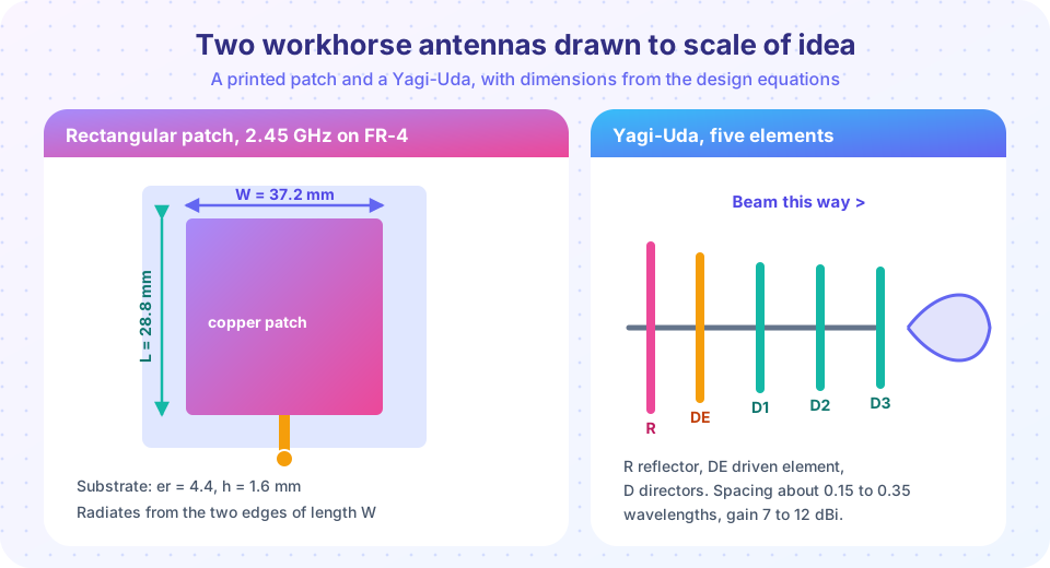
A Yagi has one driven element (a dipole), one longer reflector about 0.2 λ behind it, and several shorter directors in front. Currents in the parasitic elements are induced, and with the right lengths and spacings their phase makes the fields add in front and cancel behind. As rules of thumb:
- Reflector: about 5 percent longer than the driven element.
- Directors: about 5 percent shorter, spaced 0.15 to 0.35 λ.
- Gain grows with the number of elements: roughly 7 dBi for 3 elements and 10 to 12 dBi for 6 to 8.
- Bandwidth is narrow, a few percent, and drops as gain rises.
Impedance falls well below 73 Ω because of the mutual coupling, so Yagis use a folded dipole or a matching network.
The microstrip patch
A rectangular patch of width W and length L on a substrate of thickness h and relative permittivity εr is a resonant cavity. The fields leak from the two edges of width W; these slots radiate in phase. The design equations (for a patch on a thin substrate, W/h > 1) are:
- Width:
W = c / (2 f) · sqrt(2 / (εr + 1)) - Effective permittivity:
εeff = (εr + 1)/2 + (εr - 1)/2 · (1 + 12 h/W)^(-1/2) - Length extension (fringing):
ΔL = 0.412 h (εeff + 0.3)(W/h + 0.264) / ((εeff - 0.258)(W/h + 0.8)) - Length:
L = c / (2 f sqrt(εeff)) - 2 ΔL
Worked example, 2.45 GHz on FR-4 (εr = 4.4, h = 1.6 mm): W = 37.2 mm, εeff = 4.08, ΔL = 0.74 mm, L = 28.8 mm. The patch is a little under half a guided wavelength long, and 1 mm of error in L moves the resonance by tens of megahertz (try it below). Because L is a physical dimension to etch, real designs are simulated and tuned.
Typical patch properties: gain 5 to 8 dBi, impedance at the edge 150 to 300 Ω (lowered by an inset feed or a probe feed), fractional bandwidth 1 to 3 percent on thin substrates, linear polarization along L. A thicker, lower-permittivity substrate gives more bandwidth and efficiency at the price of size. FR-4 is lossy at GHz frequencies, so efficiency is poor; RF boards use low-loss laminates.
Common misconceptions
"A dipole must be exactly λ/2." Cut it about 5 percent short, then trim while watching the reactance or VSWR.
"A Yagi's gain comes from its extra metal." It comes from the phase of the induced currents; wrong lengths or spacings ruin it.
"A patch is wideband because it is flat." Patches are narrowband; stacking, slots or thicker substrates are needed to broaden them.
Try it
Press Run (or Ctrl + Enter) to see the result here.
Program input · what you'd type while the program runs
Type the answers before you press Run, one per line. Each time the program reads a line (with input()), it gets the next line from this box.
Press Run (or Ctrl + Enter) to see the result here.
Program input · what you'd type while the program runs
Type the answers before you press Run, one per line. Each time the program reads a line (with input()), it gets the next line from this box.
Press Run (or Ctrl + Enter) to see the console output here.
No output.
Check your understanding
Quick check · 5 questions
of 5 answered You scored / 5 · perfect!
-
1. A quarter-wave monopole over a perfect ground plane has an impedance of about
Half the dipole's 73 ohm. -
2. In a Yagi-Uda, the reflector is
A slightly longer parasitic element behind the dipole reflects power forward. -
3. Fringing fields make a patch antenna look
Each edge adds delta L, so the physical length is reduced by 2 delta L. -
4. A thicker, lower-permittivity patch substrate generally gives
Low permittivity spreads the field and lowers Q, raising bandwidth, but the patch grows. -
5. A folded dipole's impedance is about
A 2-conductor folded dipole transforms by 4, giving about 292 ohm.
Summary
- Dipole: about 0.47 λ to 0.48 λ, 73 Ω, 2.15 dBi. Monopole: λ/4, 36.5 Ω, 5.15 dBi over perfect ground.
- Yagi: reflector and directors induce currents that steer power forward; gain 7 to 12 dBi.
- Patch:
W,εeff,ΔLandLfollow four equations; bandwidth is 1 to 3 percent.
Next: Horns and dishes
Track your progress
Create a free account to tick off lessons and pick up where you left off on any device.
of RF Engineering and Antennas lessons completed