


















Lesson 27 of 46 · Antenna Fundamentals
Pattern, Gain and Directivity
Learn to read radiation patterns, measure beamwidth and sidelobes, compute directivity from the pattern, and tell directivity from gain and dBi from dBd.
If you could see radio power around an antenna, you would not see a ball of light. You would see lobes: bright where the antenna sends most of its power, dark where it does not. The radiation pattern is that picture. From it you read beamwidth, sidelobe level and the single number that matters most on a link budget: gain. This lesson shows how those quantities are defined, how to calculate them from the pattern, and what the common decibel units mean.
What you will learn
- How to read a polar and a rectangular pattern.
- How half-power beamwidth, first null beamwidth and sidelobe level are defined.
- How directivity comes from integrating the pattern, with the dipole as a worked case.
- The difference between directivity, gain, dBi and dBd.
Key terms
Radiation pattern: how radiated field or power varies with direction, at a fixed distance in the far field.
HPBW: half-power beamwidth, the angle between the points where power falls to half (-3 dB) of the peak.
Sidelobe level (SLL): the peak of the largest lobe other than the main lobe, relative to the main lobe.
Directivity D: 4π U_max / P_rad, where U is radiation intensity (W per steradian).
Gain G: G = e D, where e is radiation efficiency.
Reading a pattern
The far field starts at distances beyond 2 D_ant² / λ for a large antenna of maximum dimension D_ant. There the pattern no longer changes with distance. It is plotted in two ways:
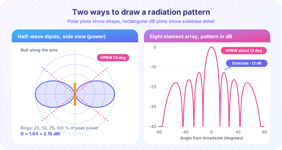
- Polar plots wrap the angle around a circle and use distance from the center for level. They show the shape at a glance: a dipole's figure eight, a dish's single thin lobe.
- Rectangular plots show angle on the horizontal axis and level in decibels on the vertical. They make low sidelobes readable, which are invisible on a linear polar plot.
Standard cuts are the E-plane (containing the electric field and the direction of maximum radiation) and the H-plane (containing the magnetic field). For a vertical dipole the E-plane is any vertical plane and the H-plane is the horizontal one.
Read these numbers from a pattern:
- HPBW: 13 degrees for the 8-element array in the figure; 78 degrees for a half-wave dipole in its E-plane.
- First null beamwidth (FNBW): angle between the first nulls on either side of the main lobe.
- Sidelobe level: about -13 dB for a uniformly excited array, lower with tapering.
- Front-to-back ratio: main lobe level divided by the level in the opposite direction.
Directivity
The total radiated power is the integral of radiation intensity over the sphere:
P_rad = ∫ U(θ, φ) dΩ
An isotropic source would have U_iso = P_rad / (4π). Directivity is how much better the peak is:
D = U_max / U_iso = 4π U_max / P_rad
For a pattern that depends only on θ (rotationally symmetric, like a dipole), this becomes D = 2 U_max / ∫₀^π U(θ) sin θ dθ.
Half-wave dipole. Its normalized pattern is U(θ) = [cos((π/2) cos θ) / sin θ]², with the peak U = 1 at θ = 90°. Numerical integration gives ∫ U sin θ dθ = 1.2188, so D = 2/1.2188 = 1.64, which is 10 log10(1.64) = 2.15 dBi.
Quick estimate from beamwidths. For a single narrow beam with half-power widths θ1 and θ2 in degrees, the beam solid angle is about θ1 θ2 square degrees and
D ≈ 41,253 / (θ1 θ2) (an overestimate for patterns with big sidelobes; practical gain is often lower, with 30,000 to 35,000 used for real antennas).
A pencil beam of 5° by 5° has D ≈ 1650 = 32 dBi.
Gain, efficiency and the dB units
Not all power fed to an antenna radiates: some heats the conductors and dielectric. The radiation efficiency e = P_rad / P_in converts directivity to gain:
G = e D
Gain is what a link budget uses. Ohmic losses lower it; mismatch loss is separate and not part of this definition (IEEE "gain" excludes mismatch).
- dBi: gain relative to an isotropic radiator. A half-wave dipole is 2.15 dBi.
- dBd: gain relative to a half-wave dipole.
dBi = dBd + 2.15.
When a vendor quotes only "dB", ask which reference it uses. A 9 dBd Yagi is 11.15 dBi.
Common misconceptions
"A directional antenna radiates more total power." Total power is set by the transmitter. A directional antenna only concentrates it.
"The 3 dB beamwidth is where there is no signal." At the half-power points you still have half the peak power. Signals exist well outside the main lobe.
"Gain in dBi and dBd are interchangeable." They differ by 2.15 dB, which is large in a link budget.
Try it
Press Run (or Ctrl + Enter) to see the result here.
Program input · what you'd type while the program runs
Type the answers before you press Run, one per line. Each time the program reads a line (with input()), it gets the next line from this box.
Press Run (or Ctrl + Enter) to see the result here.
Program input · what you'd type while the program runs
Type the answers before you press Run, one per line. Each time the program reads a line (with input()), it gets the next line from this box.
Press Run (or Ctrl + Enter) to see the console output here.
No output.
Check your understanding
Quick check · 5 questions
of 5 answered You scored / 5 · perfect!
-
1. A half-wave dipole has a gain of 2.15 dBi. In dBd that is
dBd is relative to the dipole itself, so the dipole is 0 dBd. -
2. An antenna has D = 100 and efficiency 80 percent. Its gain is
G = eD = 80, which is 10 log10(80) = 19.0 dBi. -
3. Which beam has the highest directivity estimate?
D is about 41253/(theta1 theta2), largest for the narrowest beam. -
4. On a rectangular dB plot, the half-power beamwidth is measured between points
Half power corresponds to -3 dB below the peak. -
5. A 12 dBd Yagi is how many dBi?
dBi = dBd + 2.15 = 14.15.
Summary
- A pattern shows direction dependence; HPBW and sidelobe level are the headline numbers.
D = 4π U_max / P_rad; a half-wave dipole has D = 1.64 (2.15 dBi).G = e D;dBi = dBd + 2.15.- More aperture (in wavelengths) gives a narrower beam and higher gain.
Track your progress
Create a free account to tick off lessons and pick up where you left off on any device.
of RF Engineering and Antennas lessons completed