


















Lesson 17 of 46 · S-Parameters and Microwave Networks
S-Parameter Basics: Definitions, Properties and dB
Learn what S11, S21, S12 and S22 mean, how they come from incident and reflected waves, how to read them in dB, their properties and how reference planes shift them.
S-parameters are the standard language for describing RF components. When you see S21 = −0.5 dB on a filter datasheet or S11 < −10 dB on an antenna specification, you are reading a compressed description of the whole device: how much power passes, how much bounces and with what phase. This lesson defines them carefully, then shows how to read, check and use them.
What you will learn
- The definition of the incident and reflected waves
aandb. - How each
Sijis defined and what a measurement looks like. - Properties: reciprocity, symmetry, passivity and losslessness.
- How to convert S-parameters into return loss, insertion loss and isolation in dB.
- How moving the reference plane changes the phase of S-parameters.
Key terms
- Port: a pair of terminals where a wave can enter or leave, with a reference impedance
Z0. - Incident wave (a): the wave entering a port, normalized so that
|a|²is power in watts. - Reflected wave (b): the wave leaving a port.
- Reciprocal network: a network with
S12 = S21(passive, with no ferrites or active parts). - Reference plane: the cross-section where the phase of the waves is defined.
Waves at a port
At any port the total voltage V and current I (flowing into the network) combine into two normalized waves:
a = (V + Z0 I) / (2 √Z0) (incident)
b = (V − Z0 I) / (2 √Z0) (reflected, or outgoing)
The square root normalization makes |a|² the power flowing into the port and |b|² the power flowing out, so the net power delivered to the network is |a|² − |b|². If the port is terminated in a load ZL, then a and b are related by b/a = Γ_L, the reflection coefficient of chapter 2.
The S-matrix
For an N-port, the outgoing waves are linear combinations of the incoming ones. For a two-port:
b1 = S11 a1 + S12 a2
b2 = S21 a1 + S22 a2
To measure S11 and S21, drive port 1 and put a matched load on port 2 so a2 = 0. Then
S11 = b1 / a1: reflection at port 1S21 = b2 / a1: transmission from port 1 to port 2
Swap the roles for S22 = b2/a2 and S12 = b1/a2 (with a1 = 0). A VNA does exactly this with a calibrated bridge and receiver at each port.
Worked example: a series resistor
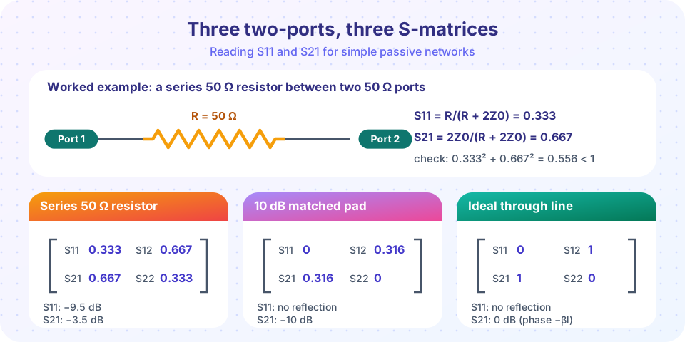
A 50 Ω resistor in series between two 50 Ω ports. Drive port 1; with port 2 matched, the 50 Ω resistor and the 50 Ω load form a 100 Ω load for the source of 50 Ω:
- Input impedance
Zin = 50 + 50 = 100 Ω, soS11 = (100 − 50)/(100 + 50) = 1/3. - The voltage at port 2 is half the voltage at port 1. In general
S21 = 2Z0/(R + 2Z0) = 100/150 = 2/3.
So S11 = 0.333 and S21 = 0.667 (both real). In dB: S11 = −9.5 dB, S21 = −3.5 dB. The power absorbed by the resistor is 1 − 0.333² − 0.667² = 44.4% of the incident power.
For a shunt 50 Ω resistor to ground the numbers are S11 = −1/3 and S21 = 2/3: a shunt element always has S21 = 1 + S11.
Reading the numbers in dB
Because |S|² is a power ratio, 20 log₁₀|S| is a power decibel value:
- Return loss
RL = −20 log₁₀|S11|.S11 = −10 dBmeans|S11| = 0.316, VSWR 1.92, 10% of power reflected. - Insertion loss
IL = −20 log₁₀|S21|for a passive part such as a filter or cable. - Gain
= 20 log₁₀|S21|for an amplifier (positive). - Isolation is
−20 log₁₀|S12|or the loss between two ports: a high number is good.
S11 and Γ are the same thing when the device is a one-port: the VSWR formula still applies, VSWR = (1 + |S11|)/(1 − |S11|).
Datasheets often write S11 = −15 dB as if it were negative return loss. The sign convention differs: S11 (dB) is negative, return loss is the same number made positive. Always check the sign.
Properties you can check
- Reciprocity:
S12 = S21for networks made of linear passive materials without ferrite. Amplifiers are not reciprocal: S12 is much smaller than S21. - Symmetry:
S11 = S22if the network looks the same from both ports. - Passive: the power coming out cannot exceed the power going in:
|S11|² + |S21|² ≤ 1(with port 2 matched), and the same for the other column. - Lossless: the S-matrix is unitary: for each column the squared magnitudes sum to exactly 1, and the columns are orthogonal.
- Matched and isolated: a perfect directional coupler or circulator has special zero entries.
A quick sanity check on any model or measurement: if the passive column sum exceeds 1, something is wrong (calibration, port numbering, or an unconstrained model).
Moving the reference plane
The waves are defined at a particular cross-section. If you add a line of electrical length θ1 at port 1 and θ2 at port 2 (a cable or fixture), the new S-parameters are
S11' = S11 e^(−j2θ1), S22' = S22 e^(−j2θ2), S21' = S12' = S21 e^(−j(θ1 + θ2))
so magnitudes are unchanged and only phase rotates. This is how de-embedding works: subtract the known delay of a fixture to see the device alone. On the Smith chart, a lossless line rotates S11 clockwise around the center by 2θ as you move the reference plane away from the device.
Touchstone files
S-parameter data is exchanged in Touchstone format (.s1p, .s2p, ...). The header line says the units and format; each data row has a frequency followed by the S-parameters. Here is the series resistor as an .s2p (an illustrative single-frequency file):
! 50 ohm series resistor, one frequency point
# GHZ S MA R 50
1.0   0.333 0   0.667 0   0.667 0   0.333 0
MA means magnitude and angle in degrees. Row order for two-ports is S11 S21 S12 S22.
Common misconceptions
- "S21 is the gain." Only for an amplifier. For a passive part, it is a loss. And
|S21|assumes both ports are terminated inZ0; in a real circuit with other terminations the available gain differs. - "S11 = 0 means no power is lost." It means nothing reflects at the input. The device may still absorb all the power.
- "S-parameters depend on the source." They are independent of the source and load if all ports are terminated in
Z0during the measurement. The reference impedance (usually 50 Ω) is part of the definition.
Try it
This tool builds S-parameters from ABCD matrices and checks all the properties from the lesson: reciprocity, symmetry and the power column sum for several two-ports, including a lossless 90° line of impedance 70.7 Ω.
Press Run (or Ctrl + Enter) to see the result here.
Program input · what you'd type while the program runs
Type the answers before you press Run, one per line. Each time the program reads a line (with input()), it gets the next line from this box.
Second, a visual of the reference-plane rule. A short circuit has S11 = −1. Adding more cable moves the reference plane away, and the measured S11 winds around the edge of the Smith chart, one full turn each time the cable grows by half a wavelength.
Press Run (or Ctrl + Enter) to see the result here.
Program input · what you'd type while the program runs
Type the answers before you press Run, one per line. Each time the program reads a line (with input()), it gets the next line from this box.
Check your understanding
Quick check · 5 questions
of 5 answered You scored / 5 · perfect!
-
1. For a 50 Ω series resistor between two 50 Ω ports, S21 equals
S21 = 2Z0/(R + 2Z0) = 100/150 = 0.667. -
2. What is the return loss for S11 = −10 dB?
Return loss is the same magnitude with the sign flipped: 10 dB. -
3. A passive reciprocal two-port has
Reciprocity means S12 = S21; symmetry is an extra condition. -
4. A lossless network has |S11| = 0.6. What must |S21| be (output matched)?
|S11|² + |S21|² = 1, so |S21|² = 1 − 0.36 = 0.64 and |S21| = 0.8. -
5. Adding a lossless cable at port 1 changes S11 by
A lossless line rotates the phase of S11 by −2θ and leaves the magnitude unchanged.
Summary
a = (V + Z0 I)/(2√Z0)andb = (V − Z0 I)/(2√Z0)are the incident and reflected power waves.Sij = b_i / a_jwith all other ports matched; S11 and S22 are reflections, S21 and S12 transmissions.- dB forms:
RL = −20 log|S11|,IL = −20 log|S21|, gain= 20 log|S21|. - Passive reciprocal parts have
S12 = S21and column power sums at most 1; lossless parts sum to exactly 1. - Reference-plane shifts rotate phase by
−2θ(reflections) or−(θ1 + θ2)(transmission).
Track your progress
Create a free account to tick off lessons and pick up where you left off on any device.
of RF Engineering and Antennas lessons completed