


















Lesson 9 of 46 · Waves and Transmission Lines
Impedance Along a Line: Stubs and Quarter-Wave Transformers
Learn how the impedance seen at the input of a line depends on its length, how shorted and open stubs act as inductors and capacitors, and how a quarter-wave section matches two resistances.
The impedance you see looking into a transmission line is not the load impedance. It depends on how long the line is, because the wave shifts phase as it travels to the load and back. A 50 Ω line ending in a short circuit can look like an open circuit from the other end. A piece of cable can behave like an inductor or like a capacitor.
This is not a nuisance. It is a toolbox. Stubs, matching sections and filters in RF circuits are made from short pieces of line precisely because their impedance can be shaped by choosing their length.
What you will learn
- The input impedance formula for a lossless line of length
l. - What a quarter-wave and a half-wave line do to a load.
- How shorted and open stubs behave as reactances.
- How to design a quarter-wave transformer to match two resistances, and how wide its band is.
Key terms
- Input impedance (Zin): the impedance seen looking into the line input with the load attached.
- Stub: a short piece of line, open or short at its far end, used as a reactive element.
- Quarter-wave transformer: a line
λ/4long with impedanceZ1 = √(Z0 · RL)that matchesZ0toRL. - Electrical length (βl): the line length in radians or degrees;
λ/4 = 90°,λ/2 = 180°. - Normalized impedance (z): impedance divided by
Z0.
The input impedance formula
For a lossless line of characteristic impedance Z0 and length l, terminated in ZL:
Zin = Z0 · (ZL + j Z0 tan βl) / (Z0 + j ZL tan βl), with β = 2π/λ.
Write t = tan βl. The formula is easy to apply by hand once you remember the three limiting results:
l = 0:Zin = ZL(no line, no change).l = λ/2(βl = π,t = 0):Zin = ZL. Every half wavelength the impedance repeats.l = λ/4(t → ∞):Zin = Z0² / ZL. The line inverts the load.
Worked example. A 50 Ω line of length λ/8 (βl = 45°, t = 1) ends in ZL = 100 Ω.
Zin = 50 · (100 + j50) / (50 + j100)
Multiply top and bottom by the conjugate of the bottom, 50 − j100:
(100 + j50)(50 − j100) = 5000 − j10000 + j2500 + 5000 = 10000 − j7500
and |50 + j100|² = 12500. So (100 + j50)/(50 + j100) = 0.8 − j0.6 and Zin = 40 − j30 Ω. A purely resistive 100 Ω load turned into a capacitive impedance simply because we put an eighth of a wavelength of cable in front of it.
Stubs: lines as reactors
A stub terminated in a short has ZL = 0, so Zin = j Z0 tan βl. An open stub has ZL → ∞, so Zin = −j Z0 cot βl.
| Stub length | Short-circuited | Open-circuited |
|---|---|---|
very short (l ≪ λ/4) |
small inductor (+jX) |
small capacitor (−jX) |
λ/8 on 50 Ω |
+j50 Ω |
−j50 Ω |
λ/4 |
open circuit | short circuit |
between λ/4 and λ/2 |
capacitive | inductive |
λ/2 |
short circuit | open circuit |
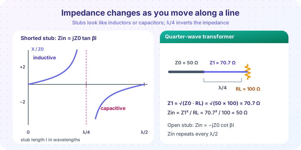
A shorted stub is inductive for its first quarter wavelength and then capacitive, as the plot shows. Choose the length to get the reactance you want: for +j25 Ω on a 50 Ω line, tan βl = 0.5, so βl = 26.6°, l = 0.074 λ.
Why use stubs? A coil or capacitor at 10 GHz would be a tiny part with large parasitics, while a stub is just a piece of printed line with exactly calculable properties. In microstrip, open stubs are more common (no via is needed); in coax, shorted stubs are easy to make.
The quarter-wave transformer
A λ/4 line with impedance Z1 between a source Z0 and a real load RL gives Zin = Z1² / RL. If we choose Z1 = √(Z0 · RL), then Zin = Z0 and the match is perfect at the design frequency.
Worked example. Match 100 Ω to 50 Ω. Z1 = √(50 × 100) = 70.7 Ω. The line is λ/4 long (at 1 GHz on a line with velocity factor 0.667, that is 50 mm) and Zin = 70.7² / 100 = 50 Ω.
Because the section is exactly λ/4 only at the design frequency, the match degrades away from it. The fractional bandwidth for a given reflection limit depends on the impedance ratio: the closer RL is to Z0, the wider the match. Stacking two or three sections gives wider bandwidth, as in the multi-section transformers of chapter 3.
A quarter-wave transformer works for real loads. If the load has a reactive part, first cancel it with a stub or a series element, or use another method such as the single-stub match of chapter 3.
Common misconceptions
- "A quarter-wave line changes the impedance by a fixed factor." It maps
ZLtoZ0²/ZL: a high load becomes low and a low load becomes high. The factor depends onZ0. - "A shorted stub is always inductive." Only for lengths below
λ/4(and in the nextλ/2cycle,λ/2to3λ/4). Betweenλ/4andλ/2it is capacitive. - "The formula needs the line to be 50 Ω." The formula holds for any
Z0; 50 Ω appears in our examples only because it is the common standard.
Try it
The first tool plots how the input impedance of a 50 Ω line terminated in 100 Ω changes with length. Notice the real part swinging between 25 Ω and 100 Ω and the reactance going positive and negative.
Press Run (or Ctrl + Enter) to see the result here.
Program input · what you'd type while the program runs
Type the answers before you press Run, one per line. Each time the program reads a line (with input()), it gets the next line from this box.
The second tool designs a quarter-wave transformer and sweeps frequency to show its reflection. Change the load to see how a smaller impedance step gives a wider band.
Press Run (or Ctrl + Enter) to see the result here.
Program input · what you'd type while the program runs
Type the answers before you press Run, one per line. Each time the program reads a line (with input()), it gets the next line from this box.
Check your understanding
Quick check · 6 questions
of 6 answered You scored / 6 · perfect!
-
1. A λ/4 section of 50 Ω line is terminated in 25 Ω. The input impedance is
Zin = Z0²/ZL = 2500/25 = 100 Ω. -
2. A λ/2 line of any impedance is terminated in ZL. The input impedance is
Every half wavelength the impedance repeats. -
3. What is the input impedance of a λ/8 shorted stub on a 50 Ω line?
Zin = jZ0 tan 45° = +j50 Ω, an inductive reactance. -
4. What characteristic impedance should a quarter-wave transformer have to match 200 Ω to 50 Ω?
Z1 = √(50 × 200) = √10000 = 100 Ω. -
5. A quarter-wave transformer matches perfectly
The section is λ/4 only at the design frequency; the match degrades on either side. -
6. An open-circuited λ/4 stub looks like
Zin = −jZ0 cot(90°) = 0: a short circuit at the design frequency.
Summary
Zin = Z0 (ZL + jZ0 tan βl)/(Z0 + jZL tan βl).λ/2repeats the load;λ/4givesZin = Z0²/ZL.- A shorted stub is
jZ0 tan βl; an open stub is−jZ0 cot βl. - A quarter-wave transformer uses
Z1 = √(Z0 RL)for real loads; bandwidth narrows as the impedance step grows. - These tools are the basis of the Smith chart in chapter 3.
Next: Chapter 2 Review
Track your progress
Create a free account to tick off lessons and pick up where you left off on any device.
of RF Engineering and Antennas lessons completed