


















Lesson 25 of 46 · Amplifiers and Mixers
Chapter Review: Amplifiers and Mixers
Review gain in dB, noise figure and the Friis cascade, P1dB and IP3, stability and mixer frequency planning with a recap table and a ten question quiz.
You have now seen the three questions every RF stage must answer: how much noise it adds, how much distortion it makes and which frequencies it creates. This review puts them on one page and tests whether you can combine them.
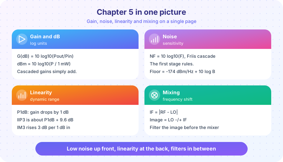
Recap table
| Topic | Key formula | Remember |
|---|---|---|
| Decibels | dB = 10 log10(P2/P1), dBm = 10 log10(P/1 mW) |
3 dB is double, 10 dB is ten times |
| Noise floor | -174 + 10 log10(B) dBm |
Wider bandwidth, more noise |
| Noise figure | Te = 290 (F - 1) |
Passive loss equals NF |
| Friis | F = F1 + (F2-1)/G1 + ... |
First stage dominates noise |
| Compression | gain falls 1 dB at P1dB | Upper limit of linear use |
| IM3 | P_IM3 = 3 P_out - 2 OIP3 |
Slope 3, IIP3 about P1dB + 9.6 dB |
| Cascade IIP3 | 1/IIP3 = 1/I1 + G1/I2 + ... |
Last stages dominate linearity |
| SFDR | (2/3)(IIP3 - floor) |
Dynamic range of clean reception |
| Stability | K > 1 and abs(Δ) < 1 |
Check across all frequencies |
| Mixer | IF = abs(RF - LO), image = RF ∓ 2 IF |
Filter the image before the mixer |
Try it
Press Run (or Ctrl + Enter) to see the result here.
Program input · what you'd type while the program runs
Type the answers before you press Run, one per line. Each time the program reads a line (with input()), it gets the next line from this box.
Press Run (or Ctrl + Enter) to see the console output here.
No output.
Check your understanding
Quick check · 10 questions
of 10 answered You scored / 10 · perfect!
-
1. A 12 dB gain stage is followed by a 3 dB loss. The net gain is
Gains and losses in dB add: 12 - 3 = 9 dB. -
2. A receiver has a 4 MHz bandwidth and NF = 5 dB. Its noise floor (dBm) is about
-174 + 66 + 5 = -103 dBm. -
3. Which ordering gives the best system noise figure?
A high gain, low noise first stage divides down later noise. -
4. Two tones at -15 dBm output each, OIP3 = +25 dBm. IM3 level?
3(-15) - 2(25) = -95 dBm. -
5. Doubling the input power of a two-tone test raises IM3 by
Doubling is +3 dB; IM3 has slope 3, so it rises 9 dB. -
6. Cascade linearity is most affected by
Late stages see the amplified signals, and their IIP3 is divided by the gain before them. -
7. A device has K = 1.5 and |Delta| = 1.2. It is
Both K > 1 and |Delta| < 1 are required. -
8. RF = 433 MHz, IF = 10.7 MHz, low-side injection. LO =
LO = RF - IF = 422.3 MHz. -
9. With that low-side LO, the image frequency is
Image = LO - IF = 411.6 MHz, which is RF - 2 IF. -
10. Why is the sum frequency discarded after the mixer?
Both products exist; the IF filter keeps only the wanted one.
Summary
- Budget noise from the front, linearity from the back.
- Use decibels and the cascade equations on every stage before choosing parts.
- Plan the IF so the image can be filtered.
Track your progress
Create a free account to tick off lessons and pick up where you left off on any device.
of RF Engineering and Antennas lessons completed