


















Lesson 22 of 46 · Amplifiers and Mixers
Noise Figure and the Cascade
Learn thermal noise, noise figure, noise temperature and the Friis cascade formula, and see why a low noise amplifier must come first in a receiver.
Every resistor, every transistor and every antenna adds a little random noise to a signal. At RF the signals can be so small that this noise decides whether you can hear a station at all. Noise figure is the single number that tells you how much a component degrades the signal to noise ratio. In this lesson you will meet the thermal noise floor, define noise figure properly, and learn the cascade formula that engineers use to budget noise for a whole receiver.
What you will learn
- How to compute the thermal noise power in a given bandwidth.
- What noise figure and noise temperature mean and how they convert.
- How to use the Friis formula for a chain of stages.
- Why lossy parts before the LNA are so expensive.
Key terms
Thermal noise: random power kTB produced by any resistive matter at temperature T in bandwidth B.
Noise factor F: ratio of input SNR to output SNR, as a plain ratio. Always at least 1.
Noise figure NF: 10 log10(F) in dB.
Noise temperature Te: equivalent temperature of a noise source that would add the same noise at the input: Te = T0 (F - 1), with T0 = 290 K.
Sensitivity: the weakest signal a receiver can decode at the required SNR.
Thermal noise: the floor under everything
A matched resistor at temperature T delivers an available noise power N = k T B, where k = 1.380649e-23 J/K is the Boltzmann constant and B is the bandwidth in hertz. At the standard reference temperature T0 = 290 K, kT0 = 4.0e-21 W/Hz, which is -174 dBm/Hz. For a bandwidth B:
N (dBm) = -174 + 10 log10(B in Hz)
A 1 MHz channel therefore has a thermal floor of -174 + 60 = -114 dBm. A 20 MHz Wi-Fi channel has -174 + 73 = -101 dBm. Wider channels see more noise, which is why wideband systems need stronger signals.
Noise figure
Pass a signal through a real device and its output SNR is worse than its input SNR, because the device adds noise of its own. The noise factor is
F = SNR_in / SNR_out
and the noise figure is NF = 10 log10(F). By convention the input noise is the thermal noise at 290 K. An ideal noiseless device has F = 1 (0 dB). A modern LNA at a few GHz can reach 0.5 to 1 dB; a typical mixer is 6 to 10 dB; a passive attenuator at room temperature has a noise figure equal to its loss. A 3 dB pad has NF = 3 dB.
Noise temperature expresses the same idea: Te = 290 (F - 1) kelvin. NF = 1 dB means F = 1.259 and Te = 75 K. NF = 3 dB means F about 2 and Te = 290 K. At very low noise figures temperature is the more convenient scale because it adds linearly.
The Friis cascade formula
For stages with noise factors F1, F2, F3 and available power gains G1, G2 (as ratios, not dB):
F = F1 + (F2 - 1)/G1 + (F3 - 1)/(G1 G2) + ...
The meaning is simple. The noise a later stage adds is referred back to the input by dividing by all the gain ahead of it. A high-gain first stage therefore shrinks the importance of everything after it.
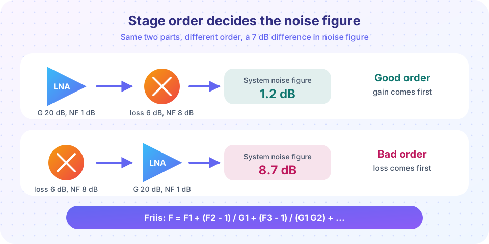
Worked example. An LNA (G = 20 dB, NF = 1 dB) feeds a mixer (conversion loss 6 dB, so G = -6 dB, NF = 8 dB).
- LNA:
F1 = 1.259,G1 = 100. - Mixer:
F2 = 10^(0.8) = 6.31. F = 1.259 + (6.31 - 1)/100 = 1.312, soNF = 1.18 dB.
Reverse the order. The mixer is first with G = 0.251, then the LNA:
F = 6.31 + (1.259 - 1)/0.251 = 7.34, soNF = 8.66 dB.
Same parts, 7.5 dB difference. This is why an LNA is placed as close to the antenna as possible, often at the mast head, rather than at the receiver end of a long cable.
The cost of losses before the LNA
A lossy element has F = L (its loss as a ratio) when it is at room temperature. Put 2 dB of cable and filter loss ahead of an LNA with NF 1 dB and the system NF becomes 2 + 1 = 3 dB (the loss has F = L and a gain of 1/L, so the LNA's excess noise is multiplied by L, which adds the dB values). Every decibel lost before the LNA is a full decibel of sensitivity lost. That is why filters ahead of the LNA are low-loss designs, and why designers fight for every tenth of a dB.
Sensitivity
Sensitivity, the weakest signal the receiver can use, follows directly:
P_min = -174 + 10 log10(B) + NF + SNR_min
A receiver with B = 1 MHz, NF = 3 dB and a demodulator that needs 10 dB SNR has P_min = -174 + 60 + 3 + 10 = -101 dBm.
Common misconceptions
"A negative gain stage has no noise effect." A lossy stage adds noise equal to its loss at room temperature. It is a noise source, not a neutral element.
"I can fix a poor first stage with a great second stage." The second stage's noise is divided by G1. If G1 is small, the second stage cannot hide the first stage's noise.
"Noise figure depends on the signal." It depends on the device, its bias and its source impedance, not on signal level, as long as the device is linear.
Try it
Press Run (or Ctrl + Enter) to see the result here.
Program input · what you'd type while the program runs
Type the answers before you press Run, one per line. Each time the program reads a line (with input()), it gets the next line from this box.
Press Run (or Ctrl + Enter) to see the result here.
Program input · what you'd type while the program runs
Type the answers before you press Run, one per line. Each time the program reads a line (with input()), it gets the next line from this box.
Press Run (or Ctrl + Enter) to see the result here.
Program input · what you'd type while the program runs
Type the answers before you press Run, one per line. Each time the program reads a line (with input()), it gets the next line from this box.
Check your understanding
Quick check · 5 questions
of 5 answered You scored / 5 · perfect!
-
1. What is the thermal noise power in a 10 MHz bandwidth at 290 K?
-174 + 10 log10(1e7) = -174 + 70 = -104 dBm. -
2. A passive 4 dB attenuator at room temperature has a noise figure of about
A lossy passive device has F equal to its loss, so NF equals its loss in dB. -
3. In the Friis formula, why is the second stage's noise divided by G1?
Dividing by the gain ahead of a stage refers its added noise to the chain input. -
4. An LNA has NF 1 dB and a 1.5 dB cable is placed before it. About what is the system NF (ignoring later stages)?
The lossy cable contributes its loss in dB, so the total is about 1.5 + 1 = 2.5 dB. -
5. A receiver has B = 2 MHz, NF = 4 dB and needs 12 dB SNR. What is its sensitivity?
-174 + 63.0 + 4 + 12 = -95.0 dBm.
Summary
- Thermal noise sets the floor:
-174 dBm/Hz + 10 log10(B). - Noise figure measures SNR degradation; noise temperature
Te = 290 (F - 1)is the equivalent. - The Friis formula divides each later stage's excess noise by the gain ahead of it.
- Losses before the LNA add directly to the system noise figure.
- Sensitivity is floor plus NF plus the SNR the demodulator needs.
Next: Linearity and stability
Track your progress
Create a free account to tick off lessons and pick up where you left off on any device.
of RF Engineering and Antennas lessons completed