


















Lesson 4 of 46 · Getting Started
Noise and the Thermal Floor
Understand thermal noise (kTB, -174 dBm/Hz), noise figure, noise temperature and how they set receiver sensitivity, with worked examples and a noise simulation.
Even with no signal present, a receiver is never silent. Charges in every conductor jitter randomly because the material is warm, and that jitter shows up as a faint hiss. This thermal noise sets the floor under every radio measurement. A signal below the floor cannot be recovered, no matter how clever the electronics. Your design goal is to keep the signal well above it and to avoid adding more noise than necessary.
This lesson gives you the formulas that turn "how sensitive is this receiver?" into a few lines of arithmetic.
What you will learn
- Why a resistor produces noise and how large it is (
N = kTB). - The handy number
−174 dBm/Hzand how to scale it to any bandwidth. - What noise figure and noise temperature measure.
- How to compute receiver sensitivity from bandwidth, noise figure and required SNR.
Key terms
- Thermal (Johnson) noise: random voltage across a conductor caused by the thermal motion of charge carriers.
- Boltzmann constant (k):
1.380649 × 10⁻²³ J/K. - Noise figure (NF): how much a device degrades the signal-to-noise ratio, in dB.
- Noise temperature (Te): the equivalent temperature of a noise source that would add the same noise.
- SNR: signal-to-noise ratio, usually in dB.
- Sensitivity: the weakest input signal that still gives the required SNR.
Thermal noise power
A resistor at temperature T (in kelvin) produces an open-circuit noise voltage with rms value
vn = √(4 k T R B)
over a bandwidth B. When you connect it to a matched load, the available noise power is the beautifully simple
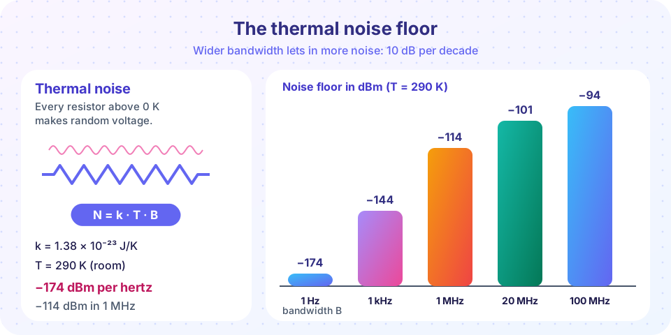
N = k T B
It does not depend on the resistance. The standard reference temperature is T₀ = 290 K (about 17 °C), so k T₀ = 4.00 × 10⁻²¹ W/Hz. In decibels relative to 1 mW:
10 log₁₀(k T₀ / 1 mW) = −174 dBm/Hz
To get the noise power in a bandwidth B, add 10 log₁₀ B:
N (dBm) = −174 + 10 log₁₀ B(Hz)
Worked example. For a 1 MHz channel 10 log₁₀ 10⁶ = 60, so N = −114 dBm. For a 20 MHz Wi-Fi channel, 10 log₁₀(2 × 10⁷) = 73.0, so N = −101 dBm. For a 1 Hz bandwidth, the floor is the famous −174 dBm.
The rms noise voltage of a 50 Ω resistor over 1 MHz at 290 K is √(4 × 1.38×10⁻²³ × 290 × 50 × 10⁶) = 0.895 µV, tiny but easily larger than a distant signal.
Noise figure
A real amplifier or mixer adds its own noise. The noise factor F is the ratio of the input SNR to the output SNR:
F = SNRin / SNRout, and the noise figure is NF = 10 log₁₀ F.
A perfect noiseless device has F = 1 (NF = 0 dB). A device with NF = 3 dB halves the SNR. Equivalently, the device acts as if the input were hotter by an amount called the equivalent noise temperature:
Te = T₀ (F − 1)
For NF = 3 dB, F = 1.995 and Te = 290 × 0.995 = 289 K: the amplifier adds as much noise as the source resistor at 290 K already contributes. For NF = 1 dB, F = 1.259 and Te = 75 K.
Chapter 5 covers how noise figures combine in a chain (the Friis formula): the first stage dominates, which is why a good low-noise amplifier goes right at the antenna.
From noise floor to sensitivity
A digital receiver needs a minimum SNR for an acceptable error rate. The weakest usable input power is the noise at the input plus the receiver's noise figure plus that required SNR:
Sensitivity (dBm) = −174 + 10 log₁₀ B + NF + SNRmin
Worked example. A receiver has B = 20 MHz, NF = 6 dB and needs SNRmin = 10 dB.
- Thermal floor:
−174 + 73.0 = −101.0 dBm. - Add the noise figure:
−101.0 + 6 = −95.0 dBm. - Add the SNR requirement:
−95.0 + 10 = −85.0 dBm.
The receiver can decode signals down to about −85 dBm. Halving the bandwidth would improve it by 3 dB; cutting the noise figure from 6 dB to 3 dB would improve it by 3 dB.
When a spec sheet quotes sensitivity, check the bandwidth and SNR it assumes. Two radios with the same sensitivity number but different bandwidths are not equally good.
Other noise sources
- Antenna noise: an antenna looking at the sky or ground picks up noise from the environment, quoted as an antenna temperature that can be well above or below 290 K depending on frequency and pointing.
- Phase noise: random jitter of an oscillator that spreads a pure tone into a skirt (chapter 5).
- Shot and flicker noise: extra noise in semiconductors; flicker (1/f) is important at low frequency.
- Quantization noise: introduced when analog values are converted to digital numbers.
Common misconceptions
- "Noise is a design flaw I can remove." Thermal noise is physics. You can only reduce the bandwidth, cool the receiver, or add gain early with a low noise figure.
- "A higher gain amplifier always improves SNR." Gain does not change the SNR of a signal already mixed with noise; a noisy amplifier lowers it. Gain only helps later stages that are noisier than the signal.
- "Noise figure and noise floor are the same." The noise floor is a power level (dBm); noise figure is a ratio (dB) describing degradation.
Try it
This tool computes the sensitivity of a receiver from your own numbers and plots it against bandwidth. Change nf_db and snr_min_db to see how each choice moves the result.
Press Run (or Ctrl + Enter) to see the result here.
Program input · what you'd type while the program runs
Type the answers before you press Run, one per line. Each time the program reads a line (with input()), it gets the next line from this box.
Next, a simulation that creates random noise voltages and measures their power. The measured level should land close to the theoretical value, with a small random scatter.
Press Run (or Ctrl + Enter) to see the result here.
Program input · what you'd type while the program runs
Type the answers before you press Run, one per line. Each time the program reads a line (with input()), it gets the next line from this box.
Check your understanding
Quick check · 6 questions
of 6 answered You scored / 6 · perfect!
-
1. What is the thermal noise power in a 10 MHz bandwidth at 290 K?
-174 + 10 log₁₀(10⁷) = -174 + 70 = -104 dBm. -
2. A receiver has a 3 dB noise figure. What does that mean for the SNR?
Noise figure is the SNR degradation through the device. -
3. Halving the bandwidth of a receiver changes its thermal noise floor by
Noise power is proportional to B, so half the bandwidth gives -3 dB. -
4. Which receiver has the best sensitivity, assuming the same SNR requirement?
Narrower bandwidth and lower noise figure both lower the floor. -
5. An amplifier with NF = 3 dB has an equivalent noise temperature of about
F = 1.995, so Te = 290 × (F − 1) ≈ 289 K. -
6. Which is true of thermal noise power kTB into a matched load?
Available noise power is kTB: it depends on temperature and bandwidth, not on R.
Summary
- Available thermal noise power is
N = kTB; at 290 K it is −174 dBm/Hz. N (dBm) = −174 + 10 log₁₀ B, so 1 MHz gives −114 dBm.- Noise figure is SNR degradation;
Te = T₀(F − 1). Sensitivity = −174 + 10 log₁₀ B + NF + SNRmin.- Narrow the bandwidth, lower the NF and add low-noise gain early to dig deeper.
Next: Chapter 1 Review
Track your progress
Create a free account to tick off lessons and pick up where you left off on any device.
of RF Engineering and Antennas lessons completed