


















Lesson 19 of 46 · S-Parameters and Microwave Networks
Passive Microwave Components: Attenuators, Dividers and Couplers
Learn how pi and T attenuators, Wilkinson power dividers and directional couplers work, with design equations, S-parameters and calculators for pads and coupling.
Between the antenna and the transistor, a typical RF system contains dozens of passive parts that do not amplify anything but are essential: attenuators set signal levels, dividers split one signal between two paths, couplers take a small sample for monitoring, and filters shape the spectrum. All of them are described by S-parameters and most are built from the pieces you already know: resistors, quarter-wave lines and coupled lines.
This lesson covers three workhorses: the resistive attenuator, the Wilkinson power divider and the directional coupler. For each one you will see the design equations and the S-parameters you should expect.
What you will learn
- How to design a matched pi or T attenuator for a given attenuation.
- How a Wilkinson divider splits power equally and keeps the outputs isolated.
- The definitions of coupling, isolation, directivity and insertion loss for a coupler.
- The effect of finite directivity on a power measurement.
Key terms
- Attenuator (pad): a resistive network that reduces power by a set number of dB and stays matched to
Z0. - Wilkinson divider: a three-port power splitter with two
λ/4arms and an isolation resistor. - Coupling (C):
−20 log₁₀|S31|, how far down the coupled port is. - Directivity (D):
D = I − Cin dB, whereIis the isolation; how well the coupler tells forward from reverse waves. - Insertion loss: loss through the main line, over and above the coupled power.
Resistive attenuators
A pi (π) pad has two shunt resistors and one series resistor. A T pad has two series resistors and one shunt resistor. Both can be designed to give any attenuation A (in dB) and to present Z0 at both ports. Let K = 10^(A/20) be the voltage ratio.
| Pi pad | T pad | |
|---|---|---|
| Shunt resistor(s) | Rsh = Z0 (K + 1)/(K − 1) |
Rp = 2 Z0 K/(K² − 1) |
| Series resistor(s) | Rse = Z0 (K² − 1)/(2K) |
Rs = Z0 (K − 1)/(K + 1) |
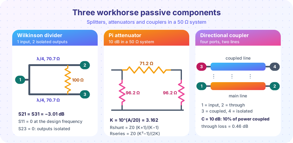
Worked example. A 10 dB pi pad in 50 Ω: K = 3.162.
Rsh = 50 × 4.162 / 2.162 = 96.2 Ω, Rse = 50 × 9 / 6.325 = 71.2 Ω
(the shunt value appears at both ends). At 3 dB the numbers become 292 Ω and 17.6 Ω, at 6 dB 150 Ω and 37.4 Ω and at 20 dB 61.1 Ω and 247.5 Ω.
Attenuators are used to lower a level, to protect a sensitive input, to improve the match between mismatched blocks (a 6 dB pad turns a VSWR 3:1 load into a much smaller reflection at the source, at the cost of 6 dB of signal) and to set the operating point of a test.
The Wilkinson power divider
A Wilkinson divider splits input power equally between two outputs. The input splits into two quarter-wave arms, each with impedance √2 Z0 = 70.7 Ω, and an isolation resistor of 2 Z0 = 100 Ω joins the two outputs.
At the design frequency:
S11 = 0(matched input).S21 = S31 = −j/√2, so each output is−3.01 dBdown: half the power each.S22 = S33 = 0(outputs matched).S23 = 0(the outputs are isolated from each other).
Why the resistor? When the two outputs have equal signals, no current flows through the resistor, so it dissipates nothing. If the output loads differ, or a signal enters one output port, the resistor absorbs the unbalance and isolates the outputs. A simple T-junction divider has none of these benefits: it cannot be matched at all three ports and its outputs are not isolated.
In microstrip the arms are curved or meandered to keep the isolation resistor close to the arm ends. A single section has a bandwidth on the order of 20% for good return loss; adding more sections widens it. Wilkinson dividers also work as combiners.
Directional couplers
A coupler is a four-port device: input (port 1), through (2), coupled (3) and isolated (4). Power entering port 1 goes mostly to port 2, with a small fraction to port 3, and ideally nothing to port 4. Power coming backward (entering port 2) goes to port 4, not port 3, which is what makes it directional.
The quantities:
- Coupling
C = −20 log₁₀|S31|, e.g. 10 dB or 20 dB. - Isolation
I = −20 log₁₀|S41|. - Directivity
D = I − C(dB): ideal is infinite; real couplers give 15 to 30 dB. - Through loss (insertion loss)
= −10 log₁₀(1 − 10^(−C/10))for an ideal lossless coupler, since the coupled power is taken from the main line.
| Coupling | Power coupled | Through loss |
|---|---|---|
| 3 dB | 50% | 3.01 dB |
| 6 dB | 25% | 1.25 dB |
| 10 dB | 10% | 0.46 dB |
| 20 dB | 1% | 0.044 dB |
| 30 dB | 0.1% | 0.004 dB |
Real parts add a small dissipative loss of a few tenths of a dB. A 20 dB coupler is the usual choice for monitoring a transmitter: 99% of the power continues, and a 1% sample (for a 10 W transmitter, 100 mW, i.e. 20 dBm) feeds a detector.
Coupler types. Coupled-line couplers use two closely spaced quarter-wave lines; the coupled port is on the same end as the input (a backward-wave coupler). Branch-line (hybrid) couplers use four quarter-wave lines in a square: with arm impedances Z0/√2 = 35.4 Ω and Z0 = 50 Ω they give an equal 3 dB split with outputs 90° apart. Rat-race couplers (a ring of 3λ/2 circumference) give sum and difference outputs. A 3 dB hybrid is a coupler with C = 3 dB.
The cost of finite directivity
A forward-power sensor on a coupler also sees part of the reflected wave from the load, leaked by the finite directivity. The leakage has the amplitude |Γ| · 10^(−D/20) relative to the forward sample and an unknown phase, so in a simple worst-case model the forward reading is off by
error (dB) = 20 log₁₀(1 ± |Γ| · 10^(−D/20))
For D = 20 dB and |Γ| = 0.2 (VSWR 1.5), 10^(−1) × 0.2 = 0.02 and the error is about +0.17 dB and −0.18 dB. For D = 10 dB it is ten times worse.
Other passive parts to know
- Circulators and isolators: non-reciprocal three-port (or two-port) devices based on ferrites that send power in one rotational direction; isolators protect amplifiers from reflections.
- Terminations: matched loads (S11 near zero) used to terminate unused ports.
- Filters (chapter 5): lowpass, highpass, bandpass; designed from prototype tables like the Butterworth filter in the previous lesson.
- Phase shifters and switches: change phase or route signals.
Common misconceptions
- "An attenuator reflects the power it removes." A matched pad absorbs the power as heat. A 20 dB pad in a 1 W line dissipates 0.99 W and must be rated for it.
- "Splitting power into two equal halves costs nothing." An ideal 2-way divider loses 3 dB per output. The Wilkinson is also not lossless in practice: the isolation resistor dissipates unbalanced power, and microstrip adds a few tenths of a dB.
- "Directivity equals isolation."
D = I − C, so directivity depends on both. A coupler with 30 dB isolation and 10 dB coupling has 20 dB directivity.
Try it
An attenuator design tool. It computes pi and T pads for several attenuations, then checks each by building the ABCD matrix and converting to S-parameters: S11 should be zero and S21 should equal the target.
Press Run (or Ctrl + Enter) to see the result here.
Program input · what you'd type while the program runs
Type the answers before you press Run, one per line. Each time the program reads a line (with input()), it gets the next line from this box.
Second, a coupler table and plot. The program lists the through loss and the coupled power for several couplings and then shows how finite directivity limits a forward-power measurement.
Press Run (or Ctrl + Enter) to see the result here.
Program input · what you'd type while the program runs
Type the answers before you press Run, one per line. Each time the program reads a line (with input()), it gets the next line from this box.
Check your understanding
Quick check · 6 questions
of 6 answered You scored / 6 · perfect!
-
1. A 6 dB matched pad in a 50 Ω system has which pi-pad shunt resistor value?
K = 2, Rsh = 50 × 3/1 = 150 Ω (to within rounding: 150.5 Ω). -
2. What is the isolation resistor value in a Wilkinson divider for a 50 Ω system?
R = 2 Z0 = 100 Ω. -
3. Each output of an ideal equal-split Wilkinson divider is
Half the power goes to each output: −3.01 dB. -
4. A coupler has 10 dB coupling and 30 dB isolation. Its directivity is
D = I − C = 30 − 10 = 20 dB. -
5. What is the through loss of an ideal 10 dB coupler?
10% of the power is coupled, leaving 90%: −10 log₁₀(0.9) = 0.46 dB. -
6. Why is the Wilkinson divider's output isolation useful?
The 100 Ω resistor isolates the outputs and dissipates the difference when the loads are unequal.
Summary
- Matched attenuators: pi pad
Rsh = Z0 (K + 1)/(K − 1),Rse = Z0 (K² − 1)/(2K), withK = 10^(A/20); a 10 dB pad is 96.2 Ω and 71.2 Ω. - Wilkinson divider: two
λ/4arms of 70.7 Ω and a 100 Ω resistor;S21 = S31 = −3 dB, outputs isolated and all ports matched. - Directional couplers: coupling
C, isolationI, directivityD = I − C; through loss−10 log₁₀(1 − 10^(−C/10)). - Finite directivity limits power-measurement accuracy.
- Pads absorb the power they remove; check the power rating.
Next: Chapter 4 Review
Track your progress
Create a free account to tick off lessons and pick up where you left off on any device.
of RF Engineering and Antennas lessons completed