


















Lesson 2 of 45 · Getting Started
Why Power Converters Switch
Learn why switching converters beat linear regulators: how a fast on-off switch, duty cycle and averaging deliver power efficiently, with worked numbers.
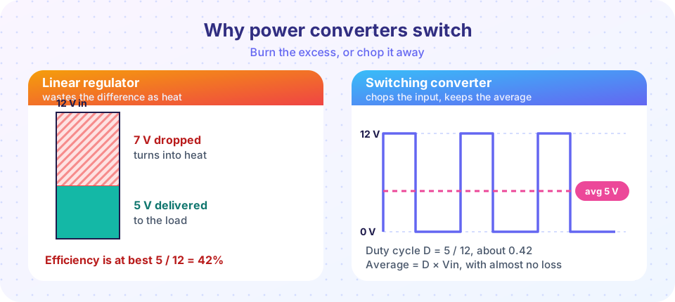
Suppose you have a 12 V battery and a 5 V device that draws 2 A. The simplest way to get 5 V is a linear regulator: a transistor that acts like a variable resistor and drops the difference. The 7 V it drops, times 2 A, becomes 14 W of heat, while the load receives only 10 W. That is a waste of more than half the energy, and the heat itself becomes a problem.
A switching converter takes a smarter approach. It never lets the transistor sit in the lossy middle. The transistor is either fully on, with almost no voltage across it, or fully off, with almost no current through it. In both states the power in the switch, V × I, is close to zero. The converter then makes the output you want by controlling how long the switch is on.
What you will learn
- Why a transistor in its linear region wastes power and a switch does not.
- What duty cycle is and how it sets the average voltage.
- How an LC filter turns a chopped waveform into smooth DC.
- Why the switching frequency is a trade-off.
Key terms
- Linear regulator: a transistor dissipating the voltage difference as heat.
- PWM (pulse-width modulation): a square wave whose on-time is adjusted to control the average.
- Duty cycle (D): on-time divided by the switching period,
D = ton / T. - Switching frequency (fsw): how many on-off cycles happen each second,
fsw = 1 / T. - Low-pass filter: a circuit that passes the slow average and blocks fast ripple.
The cost of the middle
A transistor dissipates P = V × I. In a linear regulator both are large at once: 7 V across it and 2 A through it. In a switch, think of two extremes:
- On:
Vis tiny (a MOSFET with 10 mΩ carrying 2 A drops only 20 mV), soP = 0.02 × 2 = 0.04 W. - Off:
Iis tiny (microamps), soPis microwatts.
The switch only dissipates noticeable power for the brief instants of changing state. That is why switch-mode converters are so efficient, and why their losses come mostly from the transitions, as chapter 2 will show.
Duty cycle sets the average
If a switch connects 12 V to the output for a fraction D of each period and 0 V for the rest, the output is a square wave. Its average value is
Vavg = D × Vin
For D = 0.5 the average is 6 V; for D = 5/12 ≈ 0.417 it is 5 V. Changing D changes the output without any resistor wasting power. A controller measures the output and adjusts D to keep it steady against changes in load or input, which is the topic of chapter 6.
From chopped to smooth
A square wave is not what a 5 V device wants. We add an LC low-pass filter: an inductor in series (it resists changes in current) and a capacitor across the load (it resists changes in voltage). The inductor and capacitor store energy while the switch is on and release it while the switch is off, so the load sees almost constant voltage. The cut-off frequency of the filter,
fc = 1 / (2π √(L C))
is chosen far below the switching frequency, so the ripple at fsw is strongly attenuated while the DC average passes through. For L = 22 µH and C = 47 µF, fc ≈ 4.9 kHz, and a switching frequency of 500 kHz is about 100 times higher.
Why not switch faster and faster?
A higher switching frequency lets you use smaller inductors and capacitors, so the converter shrinks. But every transition costs a little energy, and there are more transitions per second. Switching losses grow in proportion to frequency, so there is a trade-off between size and efficiency. Typical choices are tens of kHz for big, high-voltage systems and hundreds of kHz to a few MHz for small low-voltage supplies. Wide-bandgap devices (chapter 2) move that trade-off toward higher frequency.
Common misconceptions
- "The switch only passes the average voltage." The switch delivers pulses of full input voltage. It is the inductor and capacitor that average them. Without a filter the load would see the raw square wave.
- "A switching converter is always better." Not always. For tiny differences between input and output voltage, or for very low-noise analog circuits, a linear regulator can be simpler, quieter and cheaper. Many designs use a switcher followed by a low-dropout linear regulator.
Try it
A first simulation: a PWM wave at 20 kHz driving a simple RC filter. This is a stand-in model of the LC idea using the simplest possible filter, and it shows how the averaged output follows D × Vin.
Press Run (or Ctrl + Enter) to see the result here.
Program input · what you'd type while the program runs
Type the answers before you press Run, one per line. Each time the program reads a line (with input()), it gets the next line from this box.
Check your understanding
Quick check · 5 questions
of 5 answered You scored / 5 · perfect!
-
1. Why does an ideal switch dissipate almost no power?
Power is V times I. In both ideal states, one of the two factors is nearly zero. -
2. A buck converter runs from 24 V with a duty cycle of 0.25. What is its ideal average output?
Vavg = D × Vin = 0.25 × 24 V = 6 V. -
3. What does the LC filter do in a switching converter?
The inductor and capacitor store and release energy, passing the DC average and attenuating the switching-frequency ripple. -
4. What is the main downside of raising the switching frequency?
Each transition dissipates a little energy, so more transitions per second mean more switching loss. -
5. A 12 V to 5 V linear regulator supplies 1 A. How much power does it turn into heat?
It drops 7 V at 1 A, so 7 V × 1 A = 7 W.
Summary
- A linear regulator dissipates
(Vin − Vout) × Ias heat; its efficiency is at mostVout / Vin. - A switching converter turns a transistor fully on or off, so very little power is dissipated in it.
- The duty cycle
Dsets the average output,Vavg = D × Vinfor the simple chopper. - An LC filter with a cut-off far below
fswsmooths the pulses. - Higher
fswshrinks the magnetics but raises switching loss.
Track your progress
Create a free account to tick off lessons and pick up where you left off on any device.
of Power Electronics lessons completed