


















Lesson 12 of 45 · Rectifiers and AC-DC Conversion
Single-Phase Rectifiers: Half-Wave and Bridge
Work through half-wave, center-tapped and bridge rectifiers: current paths, average and rms output, peak inverse voltage, diode drops and worked examples.
The single-phase rectifier is where almost everyone's power-electronics journey starts. It uses a handful of diodes to convert the alternating mains voltage into a pulsating DC. The three versions you need to know are the half-wave rectifier (one diode), the full-wave center-tapped rectifier (two diodes and a special transformer) and the full-wave bridge (four diodes). The bridge dominates because it works from a plain transformer winding or straight from the mains.
What you will learn
- How current flows in half-wave, center-tapped and bridge rectifiers.
- How to calculate average and rms output for a resistive load.
- What peak inverse voltage (PIV) is and how to choose diodes.
- How diode drops change the answer.
Key terms
- Vpk: peak value of the AC voltage;
Vpk = √2 × Vrms. - Center-tapped transformer: a secondary with a middle terminal, giving two equal halves.
- PIV: peak inverse voltage across a blocking diode.
- Bridge rectifier: four diodes arranged in a diamond.
- Transformer utilization factor (TUF): how well the transformer's rating is used.
The half-wave rectifier
One diode in series with the load conducts only while the input is positive. The load sees the positive half-cycles and nothing during the negative halves. With ideal diodes and a resistive load:
Vavg = Vpk / π ≈ 0.318 VpkVrms = Vpk / 2PIV = Vpk- Ripple frequency: the mains frequency
f.
The half-wave rectifier is cheap, but only half of the input energy is used, and DC flows through the transformer winding, which can saturate the core. It is used only for tiny loads.
The full-wave center-tapped rectifier
A transformer with a center-tapped secondary gives two voltages, equal in size but opposite in phase. Each end feeds one diode; the center tap is the return. In each half-cycle, one diode conducts. The output equals that of the bridge: Vavg = 2 Vpk / π where Vpk is the peak of half of the secondary winding. The reverse voltage across the off diode is the full secondary peak, PIV = 2 Vpk. It uses only two diodes (low conduction loss, a single diode drop), but needs a special transformer and each half-winding works only half the time.
The full-wave bridge rectifier
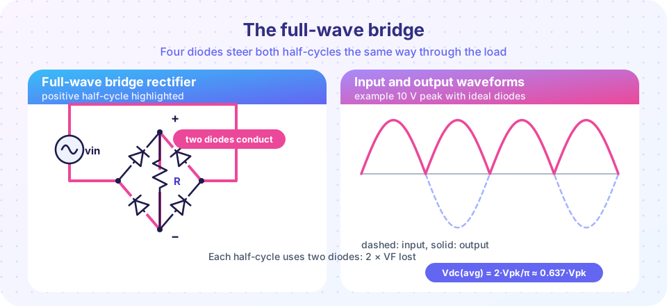
Four diodes form a diamond with the AC on two corners and the load on the other two corners. On the positive half-cycle, the diode pair on the highlighted path conducts; on the negative half-cycle, the other pair does. The load current always flows in the same direction.
Vavg = 2 Vpk / π ≈ 0.637 VpkVrms = Vpk / √2 ≈ 0.707 VpkPIV = Vpk(each blocked diode sees the peak of the input)- Ripple frequency:
2f(100 Hz for 50 Hz mains, 120 Hz for 60 Hz mains). - Two diode drops are in the current path:
Vo,pk = Vpk − 2 VF.
A worked example
A 230 V rms mains feeds a transformer with a 12 V rms secondary, wired to a bridge with silicon diodes (VF = 0.7 V).
- Peak of the secondary:
Vpk = 12 × √2 = 16.97 V. - Peak at the output:
Vo,pk = 16.97 − 2 × 0.7 = 15.57 V. - Average output (approximating the drop as constant):
Vavg ≈ 0.637 × 15.57 ≈ 9.9 Vis a quick estimate. The simulation below, which lets the diodes conduct only while the input exceeds 1.4 V, gives about 9.4 V. - With a load of
R = 10 Ω:Iavg ≈ 0.94 A(from the simulation). Each diode carries half the cycles, so its average current is about 0.47 A. - Diode PIV: about 17 V. A 50 V or 100 V rated diode is a common, safe choice.
- Loss in the diodes: two diodes conduct at any moment, so the total is about
2 × 0.7 V × 0.94 A ≈ 1.3 W(each of the four diodes loses about 0.33 W).
Compare this with the 12 V rms (about 10.8 V average) you might expect from a clean rectified 12 V rms. The two diode drops remove 1.4 V of the 17 V peak, about 8%, which is significant in low-voltage supplies and the reason Schottky diodes or synchronous rectifiers are used there.
Choosing diodes
For a bridge, choose:
VRRMat least 2 to 3 times the peak AC voltage (because of mains surges).IF(AV)at least twice the average current per diode, accounting for the peak currents seen with a filter capacitor (see the next lesson).- Inrush rating
IFSMfor the surge when the capacitor charges.
Why the bridge wins
Compared with the center-tapped circuit, the bridge needs no center tap and has a lower PIV, but has two diode drops. Compared with the half-wave circuit, it doubles the output frequency, nearly halves the ripple and uses the transformer more efficiently. For modern mains supplies, the bridge is the default.
Common misconceptions
- "The bridge output is the same as the AC rms." The average output is about 0.9 times the rms input (
0.637 × √2 = 0.9) with ideal diodes, and lower still once diode drops are included. - "PIV is twice the peak voltage in a bridge." That is true for the center-tapped circuit (and for the half-wave circuit with a filter capacitor), but in a bridge with a resistive load each diode blocks about one peak.
Try it
The simulation below builds a bridge rectifier with a 12 V rms secondary and 0.7 V diodes, driving a resistive load. It computes the average output and diode power and compares them to the numbers in the worked example. Ideal diodes with a constant forward drop are modelled; real diodes change their VF with current.
Press Run (or Ctrl + Enter) to see the result here.
Program input · what you'd type while the program runs
Type the answers before you press Run, one per line. Each time the program reads a line (with input()), it gets the next line from this box.
Press Run (or Ctrl + Enter) to see the console output here.
No output.
For 230 V rms the bridge output average is about 206 V and each diode must block at least 325 V: a 600 V or 1000 V rated diode is chosen for margin.
Check your understanding
Quick check · 5 questions
of 5 answered You scored / 5 · perfect!
-
1. A bridge rectifier is fed with 20 V peak. With two 0.7 V diode drops, what is the output peak?
20 − 2 × 0.7 = 18.6 V. -
2. What is the ripple frequency of a full-wave rectifier on 60 Hz mains?
Both half-cycles produce a pulse, so the ripple is at twice the mains frequency. -
3. What is the PIV of a diode in a center-tapped full-wave rectifier, with half-secondary peak Vpk?
When one diode conducts, the other sees the voltage of both halves, 2 Vpk. -
4. Why are silicon Schottky diodes or MOSFETs used in low-voltage bridges?
At 5 V or 12 V, two 0.7 V drops are a large fraction of the output. -
5. A half-wave rectifier gives an average of about:
Vavg = Vpk / π.
Summary
- Half-wave:
Vavg = 0.318 Vpk, ripple atf, poor transformer use. - Center-tapped: two diodes,
PIV = 2 Vpk, needs a center tap. - Bridge: four diodes,
Vavg = 0.637 Vpk,PIV = Vpk, ripple at2f, two diode drops. - Include diode drops in low-voltage designs and choose diodes with margin for PIV and surge current.
Track your progress
Create a free account to tick off lessons and pick up where you left off on any device.
of Power Electronics lessons completed