


















Lesson 15 of 45 · Rectifiers and AC-DC Conversion
Chapter 3 Review: Rectifiers and AC-DC Conversion
Review chapter 3: compare half-wave, bridge and three-phase rectifiers by average output, ripple and frequency, revisit filters and thyristors, and take a ten-question quiz.
You can now take mains AC and turn it into DC in three different ways, and you know how to smooth it and, with thyristors, to control it. This review ties the circuits together with one comparison, a numerical check and a chapter test.
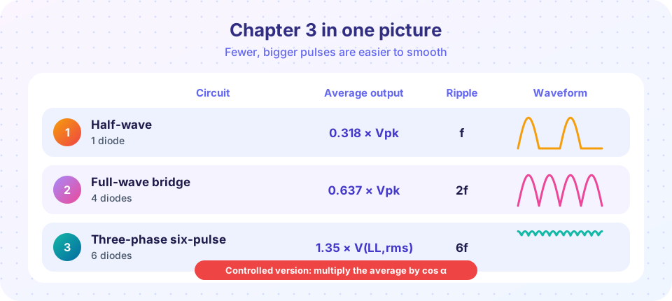
Chapter in one paragraph
A rectifier lets current flow in one direction. Half-wave uses one diode and wastes half the input; the bridge uses both half-cycles; three-phase bridges use six pulses per cycle. A capacitor smooths the output of a single-phase bridge, at the cost of pulsed input current and poor power factor. Thyristors add control: Vavg scales with cos α, and with α > 90° a line-commutated converter can send power back to the grid.
Recap table
| Circuit | Average output | Ripple frequency | Diode PIV | Notes |
|---|---|---|---|---|
| Half-wave | 0.318 Vpk |
f |
Vpk |
DC in the transformer, small loads |
| Center-tapped full-wave | 0.637 Vpk (half winding) |
2f |
2 Vpk |
one drop, special transformer |
| Single-phase bridge | 0.637 Vpk |
2f |
Vpk |
two drops, standard choice |
| Bridge plus capacitor | about Vpk − ΔV/2 |
2f |
up to Vpk |
ΔV ≈ I/(f C), pulsed current |
| Six-pulse three-phase | 1.35 VLL(rms) |
6f |
VLL,pk |
very small ripple |
| Controlled (thyristors) | scaled by cos α |
same as the diode version | as before | lower power factor |
Revisit the lessons: Single-phase rectifiers, Capacitor filters and Three-phase and thyristor rectifiers.
Worked review example
A 400 V line-to-line, 50 Hz three-phase supply feeds a diode bridge that drives a 20 A load.
- Average output:
1.35 × 400 = 540 V. - Output power:
540 × 20 = 10.8 kW. - Ripple frequency:
6 × 50 = 300 Hz. - Diode peak reverse voltage:
√2 × 400 = 566 V, so choose 1200 V diodes for margin. - Each diode carries the load current for one third of the cycle: average
20 / 3 = 6.67 A; its rms current is20 × √(1/3) = 11.5 A.
Try it
The following program compares the three rectifier types numerically: average value, rms, form factor and ripple factor with ideal diodes and no filter. The results show how the ripple factor collapses as the pulse number grows. Peak output is normalized to 1 for each circuit.
Press Run (or Ctrl + Enter) to see the result here.
Program input · what you'd type while the program runs
Type the answers before you press Run, one per line. Each time the program reads a line (with input()), it gets the next line from this box.
Check your understanding: chapter test
Quick check · 9 questions
of 9 answered You scored / 9 · perfect!
-
1. What is the ideal average of a half-wave rectified 170 V peak sine?
Vavg = Vpk / π = 170 / 3.1416 ≈ 54 V. -
2. A bridge rectifier with a smoothing capacitor delivers 2 A. The ripple frequency is 100 Hz and C = 4700 µF. Estimate ΔV.
ΔV = I/(fC) = 2/(100 × 0.0047) = 4.26 V. -
3. What is the PIV of one diode in a bridge fed with a peak of 50 V (resistive load)?
In a bridge, each blocked diode sees about the input peak. -
4. Why does a bigger filter capacitor worsen the power factor?
A shorter conduction angle means sharper current peaks and more harmonics. -
5. What is the six-pulse bridge's ripple frequency on 60 Hz mains?
6 × 60 Hz = 360 Hz. -
6. A three-phase controlled bridge on 400 V line-to-line fires at α = 30° with continuous current. Average output?
540 V × cos 30° = 540 × 0.866 ≈ 468 V. -
7. Which statement about thyristors in a line-commutated rectifier is correct?
Natural commutation by the mains turns them off, which is why they are called line-commutated. -
8. Which has the lowest ripple factor?
More pulses per cycle gives a smaller AC part. The six-pulse ripple factor is about 0.04. -
9. A 12 V rms secondary feeds a bridge with two 0.7 V diode drops. What is the output peak?
Vpk = 12 × 1.414 = 16.97 V, minus 1.4 V, equals 15.57 V.
Summary
- Pulse number rises from 1 to 2 to 6, ripple factor falls from 1.21 to 0.48 to about 0.04.
- Capacitor filters trade smooth output for spiky input current.
- Thyristor rectifiers scale the output with
cos αand can invert forα > 90°. - Rate diodes for PIV, peak and surge current, and include diode drops in low-voltage designs.
Track your progress
Create a free account to tick off lessons and pick up where you left off on any device.
of Power Electronics lessons completed