


















Lesson 13 of 45 · Rectifiers and AC-DC Conversion
Capacitor Filters and Ripple
Learn how a smoothing capacitor works after a rectifier: ripple voltage estimate, conduction angle, peak diode current, power factor and how to size the capacitor.
A rectified sine wave still rises and falls to zero a hundred times a second. Add a capacitor across the output and everything changes: the capacitor charges to the peak, then supplies the load while the input dips, and the output becomes nearly flat DC with a small ripple. This is the circuit inside almost every mains-powered electronic product, and understanding it explains both its strength (cheap, smooth DC) and its weakness (spiky current drawn from the mains).
What you will learn
- How the capacitor and diodes share the work in each cycle.
- The ripple estimate
ΔV ≈ I / (f × C)and how to sizeC. - Why diode current flows in short, tall pulses and what that does to power factor.
- What ESR and ripple-current rating mean for the capacitor.
Key terms
- Ripple voltage (ΔV): the peak-to-peak variation on the filtered DC output.
- Conduction angle: the portion of each cycle during which the diodes conduct.
- Inrush current: the surge when an uncharged capacitor is first connected.
- ESR: equivalent series resistance of a capacitor, which heats it and adds ripple.
- Power factor (PF): real power divided by apparent power.
What happens in one cycle
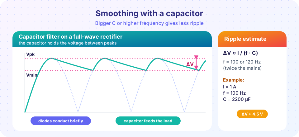
Look at the picture from left to right. Near the peak of the rectified wave, the input voltage is higher than the capacitor voltage, so a pair of diodes conducts and recharges the capacitor while also feeding the load. As the input falls, it dips below the capacitor voltage, the diodes turn off, and the capacitor alone supplies the load current, so its voltage falls (nearly linearly if the ripple is small). Then the next peak arrives and the diodes conduct again.
If the load draws a nearly constant current I, the capacitor loses charge I × t while the diodes are off. The time between peaks is T = 1/f, where f is the ripple frequency: 100 Hz or 120 Hz for a full-wave rectifier on 50 Hz or 60 Hz mains. The diodes conduct for a short time, so almost the whole period is a discharge, and the voltage drop is ΔV = I × T / C:
ΔV ≈ I / (f × C)
This is a conservative estimate (slightly too high), good for sizing.
Worked example: sizing the capacitor
A 12 V supply must deliver 1 A with no more than 1 V of ripple from a full-wave rectifier on 50 Hz mains (100 Hz ripple).
C ≥ I / (f × ΔV) = 1 / (100 × 1) = 10 mF = 10,000 µF
With a smaller ripple budget of 4.5 V, a 2200 µF capacitor gives ΔV ≈ 1 / (100 × 0.0022) = 4.5 V, which matches the picture. Note how big these capacitors are: at 100 Hz, capacitors in the range of thousands of microfarads are needed for amp-level loads. This is a main reason designers switch to high-frequency switching converters, where the same ripple needs a thousand times less capacitance.
The output DC value is not the peak but somewhat lower. A good estimate is Vdc ≈ Vpk − ΔV/2. With 17 V peak and 4.5 V ripple, the average output is about 14.75 V, before diode drops.
Diode current: short and tall
The diodes must replace the charge lost during the whole discharge in a short conduction angle. If the conduction time is a tenth of the period, the diode current during conduction is roughly ten times the average load current, with peaks reaching even more. A supply drawing 1 A of load current can easily see 5 to 10 A peaks in the diodes and in the transformer or the mains. The consequences:
- Diodes must be rated for the peak and surge currents, not just the average.
- Transformer windings, fuses and wiring suffer extra rms heating.
- The mains current is a train of narrow pulses with a low power factor, typically 0.5 to 0.7, and many harmonics.
- At the first moment of power-up, the empty capacitor draws a large inrush current, limited only by wiring and ESR; designers use inrush limiters (NTC thermistors or soft-start circuits).
A bigger capacitor makes the ripple smaller, but it narrows the conduction angle and makes the pulses taller. That is the trade-off.
Capacitor selection
Aluminium electrolytic capacitors are common for bulk storage. Check three things:
- Voltage rating: above the peak output voltage with margin (for 325 V peak, 400 V or 450 V parts).
- Ripple-current rating: the capacitor carries the pulsed current, which heats it through its ESR (
P = Irms² × ESR). Heat shortens its life; a rule of thumb is that every 10 °C increase in core temperature halves the life. - ESR: lower ESR means less heating and less extra ripple (
ΔV_esr ≈ Ipeak × ESR).
Why do big supplies add PFC?
The pulsed mains current causes poor power factor and harmonic currents that overload neutral conductors and distort the grid voltage. Standards such as IEC 61000-3-2 limit harmonics for equipment above certain power levels. The usual fix is an active power-factor correction stage: a boost converter after the bridge that forces the input current to follow the voltage as a sine wave, giving a power factor close to 1. We will meet the boost converter in chapter 4.
Common misconceptions
- "A bigger capacitor is always better." It reduces ripple but increases inrush current and makes the diode pulses narrower and taller, with worse power factor and more heating.
- "The output equals the peak voltage." It is the peak minus about half the ripple, minus diode drops, and drops further under heavy load.
Try it
Experiment with the ripple formula in the interactive demo. It simulates a full-wave bridge with ideal diodes and a constant-current load (an idealised model) and compares the simulated ripple with the estimate I / (f C). Try 50 Hz and 60 Hz, and change the capacitor.
The same logic in a script lets you look at the diode current as a function of time. The model below treats the diode as conducting whenever the rectified input is above the capacitor voltage. The peak current depends strongly on the time step near the switching instant, so read it as an order-of-magnitude indication, not as a precise prediction.
Press Run (or Ctrl + Enter) to see the result here.
Program input · what you'd type while the program runs
Type the answers before you press Run, one per line. Each time the program reads a line (with input()), it gets the next line from this box.
Check your understanding
Quick check · 4 questions
of 4 answered You scored / 4 · perfect!
-
1. A full-wave rectifier on 50 Hz mains supplies 0.5 A to a load with a 1000 µF capacitor. Estimate the ripple.
f = 100 Hz, so ΔV = I/(fC) = 0.5 / (100 × 0.001) = 5 V. -
2. What happens to the diode current pulses if you double the capacitor?
A bigger capacitor gives less ripple, so the diodes conduct for a shorter part of each cycle and the pulses are taller. -
3. Why is the capacitor ripple-current rating important?
Ripple current causes self-heating, and heat is the main aging factor for electrolytic capacitors. -
4. Typical power factor of a simple capacitor-input rectifier is about:
Narrow current pulses lower the power factor to about 0.5 to 0.7.
Summary
- A smoothing capacitor charges at the peaks and feeds the load between them.
ΔV ≈ I / (f × C)withf= ripple frequency (twice the mains for a bridge).- Diodes carry short, tall pulses: rate them for peak and surge current.
- The capacitor needs the right voltage, ESR and ripple-current rating.
- The poor power factor of this circuit is why larger supplies use PFC.
Track your progress
Create a free account to tick off lessons and pick up where you left off on any device.
of Power Electronics lessons completed