


















Lesson 38 of 45 · Applications: Solar, EVs and Power Supplies
Electric vehicle power electronics
Follow energy through an electric vehicle: battery, traction inverter, onboard and DC fast chargers, 12 V converter, 800 V systems, regenerative braking and the energy needed to drive.
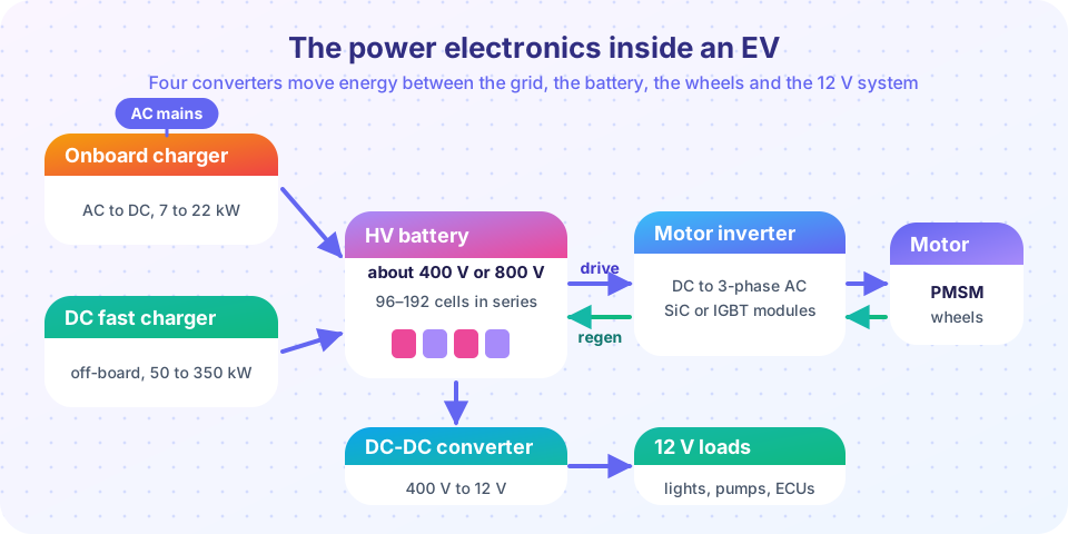
An electric car is a drive system and a power plant on wheels. At the center sits a high-voltage battery of a few hundred volts; around it are four power converters that move energy between the grid, the battery, the wheels and the low-voltage electronics. The whole vehicle is a case study in the trade-offs of this course: efficiency (because every lost watt costs range), power density (because every kilogram costs range), thermal management and safety.
This lesson explains what each converter does, why some carmakers moved from 400 V to 800 V, and how much energy a car needs, so that you can put numbers on range and charging time.
What you will learn
- Name the four converters of an EV and the power level of each.
- Explain why higher battery voltage (800 V) helps charging and what silicon carbide adds.
- Calculate battery pack voltage, charging power and charging time.
- Estimate the power needed to drive at constant speed and the effect of regenerative braking.
- Describe the safety systems of a high-voltage vehicle.
Key terms
HV battery: the traction battery pack, typically 350 to 450 V nominal (a "400 V" system) or about 700 to 800 V nominal.
Traction inverter: the three-phase inverter that drives the traction motor.
OBC (onboard charger): the AC-to-DC charger inside the vehicle (typically 7 to 22 kW).
DC fast charging: an off-board charger (50 to 350 kW) that supplies DC directly to the battery.
Regenerative braking: using the motor as a generator, with the inverter acting as a rectifier, to return braking energy to the battery.
The four converters
- Traction inverter. A three-phase inverter, exactly as in Chapter 5, between the HV battery and the traction motor (usually a permanent-magnet synchronous motor controlled with field-oriented control). Power ranges from 50 kW in small cars to 300 kW or more in performance models. Peak efficiency is 97 to 99 %. It is liquid-cooled and often integrates the DC-link capacitor and the motor controller in one module. During braking the power flows backwards: the motor generates, the inverter rectifies, and the battery is charged.
- Onboard charger (OBC). It converts the AC mains (single- or three-phase) into the battery's DC. It is a two-stage design: a PFC boost or totem-pole stage (see the supplies lesson) followed by an isolated DC-DC stage (an LLC resonant converter or a dual active bridge). Typical ratings are 7.4 kW (single-phase 32 A) or 11 kW (three-phase 16 A), and 22 kW in some vehicles. Bidirectional versions allow vehicle-to-load and vehicle-to-grid.
- DC fast charger (off-board). The power electronics are in the charging station: an active-front-end rectifier with PFC and isolated DC-DC modules, 50 to 350 kW. The vehicle's contactors connect the station straight to the battery. Because the station cannot know the battery's state, the vehicle's battery management system commands the charging current.
- DC-DC converter to 12 V (sometimes called the LDC). A few kilowatts, isolated, feeding the 12 V network of lights, pumps and computers. It replaces the alternator of a combustion car.
Why 800 V?
The relationship P = V·I is the whole story. A 150 kW charger at 400 V must supply 375 A; at 800 V it supplies 188 A. Cables and connectors can be thinner, and the conduction loss I²R in the cable and in the pack's busbars falls by a factor of four for the same resistance. The charging time falls because the current limit of a cable is no longer the bottleneck. Higher voltage also reduces motor current for a given power, so the inverter can use smaller current-rated devices.
The price is that the semiconductors must block more voltage. A 400 V bus uses 650 V devices; an 800 V bus calls for 1200 V devices. At 1200 V silicon IGBTs lose a lot to switching and carry a fixed conduction offset (Vce,sat); silicon-carbide MOSFETs switch faster with much less loss and behave as a resistor, so they are more efficient at partial load, which is where a car spends most of its time. A pack of about 96 cells in series at 3.65 V nominal gives 350 V; 192 cells give 700 V nominal (800 V at full charge).
Safety is a design driver. High-voltage systems have orange cabling, a pre-charge circuit that limits the inrush into the DC-link capacitor before the main contactors close, an interlock loop, an insulation monitor that checks that the HV system is isolated from the chassis, and pyrotechnic or electronic disconnects that open the battery in a crash.
How much energy does it take to drive?
At a steady speed v the traction power is the sum of aerodynamic drag, rolling resistance and (on slopes or when accelerating) other terms:
P_wheel = ½ · ρ · Cd · A · v³  +  Crr · m · g · v  +  m · a · v
P_battery = P_wheel / η_drivetrain          (η ≈ 0.85 to 0.92, battery to wheel)
Take ρ = 1.2 kg/m³, Cd = 0.25, A = 2.3 m², Crr = 0.009, m = 1,800 kg. At 100 km/h (27.8 m/s) the aerodynamic term is about 7.4 kW and the rolling term about 4.4 kW, so about 12 kW at the wheels; with η = 0.9 the battery supplies 13 kW, or 13 kW / 100 km/h = 13 kWh per 100 km. Because drag grows with v² per metre, at 130 km/h the consumption is far higher. In the city, drag is small and the dominant term is acceleration; regenerative braking returns part of the kinetic energy, typically recovering 50 to 70 % of what braking would waste, which improves city consumption by roughly 15 to 25 %.
Charging time
Charging power is limited by the charger, the cable and the battery. In a constant-power stage, the energy added is ΔE = P · t · η_charger. Charging from 10 % to 80 % of a 75 kWh pack needs 0.7 × 75 = 52.5 kWh. At 11 kW AC (92 % efficient) that takes about 5.2 hours; with a 150 kW DC charger and the assumed taper above 50 % state of charge, about 30 minutes (second example below). The battery's own limits (cell temperature and voltage) produce the taper, which is why the last 20 % takes as long as the first 80 %.
Common misconceptions
"A bigger inverter is always better for efficiency." An oversized inverter runs at light load, where fixed losses dominate. SiC devices help because their loss falls with current.
"Regenerative braking recovers all the energy." It recovers a good part, but the losses in the motor, inverter and battery (charge and discharge) mean that the round trip is only about 60 to 70 %. Friction brakes are still needed.
"Fast charging power is whatever the station says." The vehicle commands the current; battery temperature and state of charge limit it.
Try it
The first example computes the road-load power and the consumption per 100 km at constant speeds from 30 to 140 km/h, and shows the share of aerodynamic drag. It uses the equations above with typical parameters.
Press Run (or Ctrl + Enter) to see the result here.
Program input · what you'd type while the program runs
Type the answers before you press Run, one per line. Each time the program reads a line (with input()), it gets the next line from this box.
The second example simulates a charging session of a 75 kWh pack from 10 % to 80 % for three chargers. The DC fast charger's power is assumed to taper above 50 % state of charge. The model is a simplified assumption, not data from a particular car.
Press Run (or Ctrl + Enter) to see the result here.
Program input · what you'd type while the program runs
Type the answers before you press Run, one per line. Each time the program reads a line (with input()), it gets the next line from this box.
The third example is an EV range and charging calculator. Choose the battery size, consumption and charger power; it reports the range of a full pack and the kilometres added in ten minutes. It ignores temperature and taper.
Check your understanding
Quick check · 5 questions
of 5 answered You scored / 5 · perfect!
-
1. A pack has 100 cells in series with a nominal 3.6 V each. What is its nominal voltage?
100 × 3.6 V = 360 V. -
2. A 100 kW charger works at 800 V. What is the charging current?
I = P / V = 100,000 / 800 = 125 A. -
3. Why does 800 V help fast charging?
P = V·I: doubling voltage halves current for the same power. -
4. What happens in the traction inverter during regenerative braking?
The motor becomes a generator and the switches (and their diodes) rectify its output. -
5. How long does 52.5 kWh take at 11 kW with 92 % charger efficiency?
52.5 / (11 × 0.92) = 5.19 h.
Summary
- An EV has four converters: traction inverter, onboard charger, DC fast charger (off-board) and a DC-DC to 12 V.
- Higher battery voltage reduces current for the same power, which helps charging; 1200 V SiC MOSFETs make 800 V systems efficient.
- Driving power:
½ρCdA·v³ + Crr·m·g·vplus acceleration; regeneration recovers a good part of the kinetic energy. - Charging time is energy divided by power times efficiency, with a taper set by the battery.
- Safety systems (pre-charge, isolation monitoring, disconnects) are part of the power-electronics design.
Track your progress
Create a free account to tick off lessons and pick up where you left off on any device.
of Power Electronics lessons completed