


















Lesson 9 of 45 · Power Semiconductors
IGBTs, Thyristors and Wide-Bandgap Devices
Compare IGBTs, thyristors, SiC MOSFETs and GaN transistors: structure, conduction and switching behavior, typical ratings, gate drive and where each device wins.
Silicon MOSFETs are superb below a few hundred volts, but the resistance of a high-voltage MOSFET grows quickly with its voltage rating. At 1200 V or more, a different device takes over: the IGBT. For the very highest powers, the thyristor is still unbeaten. And in the last decade, wide-bandgap materials, silicon carbide (SiC) and gallium nitride (GaN), have reshaped the field by switching faster, running hotter and wasting less energy.
What you will learn
- How an IGBT combines a MOSFET input with a bipolar output, and what the tail current is.
- When a thyristor (SCR) is the right choice and how it turns off.
- Why SiC and GaN switch faster and conduct better at high voltage.
- Practical differences in gate drive and layout.
Key terms
- IGBT (insulated-gate bipolar transistor): a MOS-gated bipolar device for high voltage and current.
- VCE(sat): the on-state collector-emitter voltage of an IGBT.
- Tail current: the slowly decaying current when an IGBT turns off.
- Thyristor (SCR): a four-layer device that latches on after a gate pulse.
- HEMT: high-electron-mobility transistor, the structure of most GaN power devices.
The IGBT
An IGBT has a MOSFET-like gate on the input side and a bipolar transistor on the output side. A voltage on the gate turns it on without needing much gate current, like a MOSFET. But in the on state, minority carriers are injected into the thick drift region, which sharply lowers the on-state resistance of a high-voltage device. The result is a conduction voltage drop that is nearly constant:
VCE(on) ≈ V0 + r × I
with V0 around 0.8 to 1 V and typical VCE(sat) of 1.5 V to 2.5 V at rated current. Compare this with a 1200 V silicon MOSFET, whose RDS(on) would give a much larger drop at high current. That is why IGBTs win at high voltage and high current.
The price is switching speed. When the gate turns off, the stored minority carriers must decay, producing a tail current that lasts hundreds of nanoseconds to microseconds. Tail current increases turn-off loss, so IGBTs are usually switched at a few kHz to about 20 kHz in drives and up to roughly 50 kHz in optimized designs. Typical IGBT voltage ratings are 600 V, 1200 V, 1700 V and up to 6.5 kV, in discrete packages and in power modules carrying hundreds of amps. They are almost always paired with a fast anti-parallel diode.
Thyristors (SCRs)
A thyristor is a four-layer PNPN device. A short pulse at the gate turns it on; it then latches and keeps conducting even when the gate signal vanishes. It turns off only when the anode current falls below the holding current, which in a mains rectifier happens naturally at every current zero crossing. This is called line commutation.
Thyristors are rugged, cheap per kilowatt and available with ratings of several kilovolts and thousands of amps, which makes them the choice for high-voltage direct-current (HVDC) transmission, large motor starters, big controlled rectifiers and welding supplies. Their weakness is that you cannot turn them off with the gate, and they are slow. Variants include the TRIAC (conducts in both directions, used in light dimmers) and the GTO and IGCT, which can be turned off through the gate and appear in very high-power drives.
Wide-bandgap devices
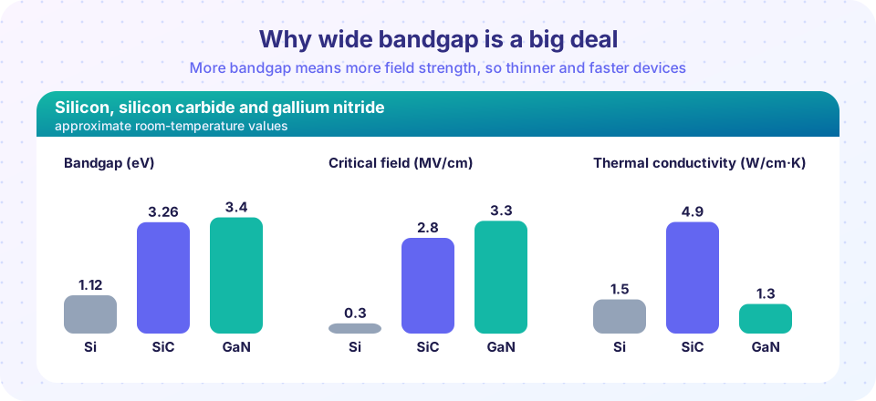
Bandgap is the energy a carrier needs to jump into the conducting state. Silicon has about 1.12 eV; 4H-SiC about 3.26 eV; GaN about 3.4 eV. A wider bandgap gives a much higher critical electric field before breakdown, roughly ten times that of silicon. This means that for the same voltage rating the active layer can be about ten times thinner and more heavily doped, which cuts resistance dramatically and shrinks capacitances. The result is lower conduction and switching loss.
Silicon carbide (SiC) MOSFETs
SiC MOSFETs cover 650 V to 3.3 kV and beyond. They switch with very little tail, handle junction temperatures up to 175 °C or more, and SiC has high thermal conductivity. They are rapidly replacing IGBTs in electric-vehicle inverters, solar inverters and fast chargers, because lower loss means smaller cooling and longer range. Gate drives typically use about +18 V to +20 V for turn-on and 0 V to −5 V for turn-off, and need clean, fast signals. The body diode of a SiC MOSFET is usable, but its voltage drop is higher than silicon.
Gallium nitride (GaN) transistors
GaN power devices are typically lateral HEMTs, built on a silicon or SiC substrate, with ratings from about 15 V to 650 V. They have tiny gate charge and no body diode (they conduct in reverse as a channel with a voltage drop, and have no reverse recovery). They can switch at hundreds of kHz to several MHz, which allows very compact adapters and data-center supplies. Enhancement-mode GaN gates are delicate: the maximum gate voltage is about 6 V, so the drive must be precise, and layout inductance has to be extremely low.
Choosing a device: a quick guide
| Situation | Often chosen |
|---|---|
| Under about 200 V, high frequency | Silicon MOSFET (or GaN for compactness) |
| 400 V to 650 V, high efficiency, compact | GaN or SiC MOSFET, or super-junction Si MOSFET |
| 1200 V to 1700 V, drives and inverters | SiC MOSFET or IGBT |
| Above 3 kV, megawatts, mains frequency | IGBT modules, thyristors, GTO/IGCT |
| Cost-sensitive mains-frequency rectifier | Silicon diodes and thyristors |
Common misconceptions
- "Wide-bandgap means no losses." SiC and GaN lose much less, but they still have conduction and switching losses. Faster edges also raise noise and can cause voltage overshoot if layout inductance is not controlled.
- "A thyristor can be turned off by removing the gate signal." It cannot; it stays on until the current falls below the holding current or the circuit reverses the voltage.
Try it
First compare conduction loss of an IGBT and a MOSFET of the same voltage class. The IGBT is modelled as V0 + r × I, the MOSFET as R × I², with illustrative numbers. Below the crossover current the MOSFET loses less, and above it the IGBT does.
Press Run (or Ctrl + Enter) to see the result here.
Program input · what you'd type while the program runs
Type the answers before you press Run, one per line. Each time the program reads a line (with input()), it gets the next line from this box.
Now compare total loss against switching frequency for a silicon IGBT and a SiC MOSFET at the same operating point. Each switching energy is the energy lost per on-off cycle. The numbers are example values chosen to show the trend, not data for any product.
Press Run (or Ctrl + Enter) to see the result here.
Program input · what you'd type while the program runs
Type the answers before you press Run, one per line. Each time the program reads a line (with input()), it gets the next line from this box.
At 5 kHz the gap is modest; at 50 kHz the IGBT loses more than twice as much. This is why SiC is used where frequency is high or efficiency is rewarded.
Check your understanding
Quick check · 5 questions
of 5 answered You scored / 5 · perfect!
-
1. What is the main reason IGBTs beat silicon MOSFETs at 1200 V and high current?
Minority carriers injected in the drift region lower the on-state resistance of a high-voltage device. -
2. What is the tail current in an IGBT?
Stored carriers decay gradually after the gate turns off, extending the overlap of voltage and current. -
3. How is a conducting thyristor turned off?
A thyristor latches; the circuit must bring the current below holding or reverse the voltage. -
4. Silicon has a bandgap of 1.12 eV. What is the approximate bandgap of 4H-SiC?
4H-SiC has about 3.26 eV, almost three times silicon. -
5. Which statement about enhancement-mode GaN transistors is true?
GaN gates are delicate: the margin between the on voltage and the absolute maximum is small.
Summary
- IGBTs give a low, nearly constant on-state drop at high voltage but have tail current, so they run at low frequency.
- Thyristors latch; they are the king of very high power at line frequency.
- SiC and GaN have a wide bandgap, high critical field and fast switching with lower loss and higher temperature capability.
- Choose by voltage, current and frequency; layout and gate drive matter more with faster devices.
Track your progress
Create a free account to tick off lessons and pick up where you left off on any device.
of Power Electronics lessons completed