


















Lesson 23 of 45 · Inverters and Motor Drives
Three-phase inverters and six-step operation
Learn the six-switch three-phase bridge: switch numbering, the six-step sequence, phase and line voltages, harmonics, THD and the current in an RL load.
Three-phase power is the language of industry: generators, transmission lines and large motors all speak it. A three-phase inverter produces that language from a DC link using just three legs, six switches and a pattern of gating signals that repeats every 60 degrees. It is easily the most important circuit in this course, because the same bridge sits inside every motor drive, every grid-tied solar inverter and every electric-vehicle traction unit.
In this lesson you will use the simplest switching pattern, six-step operation, to learn how the bridge works, derive its voltages, and see what an inductive load does to its current.
What you will learn
- Number the six switches and describe the six-step gating sequence.
- Compute pole, phase and line voltages for each 60° sector.
- Derive the rms and fundamental values of the line voltage:
0.816 Vdcand0.780 Vdc. - Explain why triplen harmonics vanish and which harmonics remain.
- Predict the current in a series RL load driven by a six-step phase voltage (THD about 6 % for the example load).
Key terms
Pole voltage: the voltage of a leg's midpoint relative to the negative DC rail; it is either 0 or Vdc.
Phase voltage: the voltage across one winding of a Y-connected load, measured from the load's neutral point.
Line voltage: the voltage between two phases, for example vab = van − vbn.
Six-step operation: each switch conducts for 180° and the state changes every 60°.
Triplen harmonics: harmonics whose order is a multiple of three (3, 9, 15, …).
Switch numbering and the six states
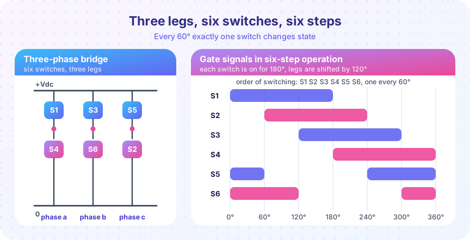
Each leg has an upper and a lower switch. The common numbering follows the order in which they turn on: S1 (upper, phase a), S2 (lower, phase c), S3 (upper, phase b), S4 (lower, phase a), S5 (upper, phase c) and S6 (lower, phase b). In each leg the upper and lower switch are complementary: S1/S4 for leg a, S3/S6 for leg b and S5/S2 for leg c. Describe the bridge state by three bits (a b c), where 1 means the upper switch of that leg conducts.
Eight states exist. (0 0 0) and (1 1 1) short all three terminals together and put zero volts across the load, so they are called zero states. The other six are the active states. Six-step operation walks through the active states in order, spending 60° in each.
Because the three legs are never in the same state at the same time (they are 120° apart), the sum of the pole voltages and the load neutral behave as follows. For a balanced Y-connected load with an isolated neutral:
van = Vdc · (2a − b − c) / 3
vbn = Vdc · (2b − a − c) / 3
vcn = Vdc · (2c − a − b) / 3
vab = Vdc · (a − b)
Here a, b, c are 0 or 1. Working through the six sectors gives the staircase below.
| Angle | Switches on | State (a b c) | van / Vdc |
vab / Vdc |
|---|---|---|---|---|
| 0°–60° | S1 S5 S6 | 1 0 1 | +1/3 | +1 |
| 60°–120° | S1 S2 S6 | 1 0 0 | +2/3 | +1 |
| 120°–180° | S1 S2 S3 | 1 1 0 | +1/3 | 0 |
| 180°–240° | S2 S3 S4 | 0 1 0 | −1/3 | −1 |
| 240°–300° | S3 S4 S5 | 0 1 1 | −2/3 | −1 |
| 300°–360° | S4 S5 S6 | 0 0 1 | −1/3 | 0 |
The phase voltage is a six-step staircase (hence the name), while the line voltage is a quasi-square wave with 120° pulses and 60° zero intervals.
Voltages and harmonics
From the table you can evaluate the rms values directly:
line voltage:   vab,rms² = (2/3)·Vdc²   →  vab,rms = 0.8165 · Vdc
phase voltage:  van,rms² = (2/9)·Vdc²   →  van,rms = 0.4714 · Vdc
The fundamental of the line voltage is a quasi-square wave with 120° wide pulses, so (use the formula from the previous lesson with pulse width α = 120°):
vab,1 (peak) = (4·Vdc/π) · sin(60°) = 1.1027 · Vdc
vab,1 (rms)  = 1.1027 · Vdc / √2 = 0.7797 · Vdc = (√6/π) · Vdc
van,1 (peak) = 2·Vdc/π = 0.6366 · Vdc
Three more facts follow from symmetry:
- Because the three phases are shifted by 120°, any harmonic whose order is a multiple of 3 is in phase in all three phases. In a line voltage (the difference of two phases) it cancels. So the line voltage contains only harmonics of order
6k ± 1: 5, 7, 11, 13, …, with amplitudes1/nof the fundamental. - The THD of the six-step line voltage is
√(0.6667 − 0.7797²) / 0.7797 ≈ 31 %. - The phase voltage to the DC midpoint (not to the load neutral) would contain triplens, but the neutral of a Y-connected load with no neutral wire sits at the common-mode average, which removes them from the load.
Worked example. A drive has a DC link of 600 V. Six-step operation gives vab,rms = 0.8165 × 600 = 490 V including harmonics, of which 0.7797 × 600 = 468 V is the useful fundamental. This is the largest fundamental a three-phase two-level bridge can produce without overmodulation tricks: the six-step limit sets the ceiling for every modulation scheme in Chapter 6.
The current in a load
An inductive load smooths the current. For a Y-connected series RL load, each phase obeys L·di/dt = van − R·i. Take R = 5 Ω, L = 20 mH at 50 Hz: the inductive reactance is 2π·50·0.02 = 6.28 Ω at the fundamental, but at the 5th harmonic it is five times larger, at the 7th seven times larger. The low-order harmonics of the voltage (each 1/n of the fundamental) are therefore attenuated by roughly 1/n once more, and the current ends up with a distortion far below the voltage's 31 %. This is why a plain six-step inverter can drive a motor acceptably but would be useless without a filter for most other loads.
The antiparallel diodes carry the part of each current cycle in which the current flows opposite to the voltage, exactly as for the single-phase bridge.
Common misconceptions
"The current always flows through the switch that is switched on." With an inductive load the current may flow in the opposite direction, and then the antiparallel diode of that switch carries it instead.
"The line voltage rms equals Vdc/√2." That is true for a sine of peak Vdc. For six-step it is Vdc·√(2/3) = 0.816 Vdc, and the useful fundamental is only 0.780 Vdc.
"A three-phase inverter needs a neutral wire." A balanced three-phase load with isolated neutral works with three wires; the three phase currents sum to zero.
Try it
The first example generates the six-step gating from the switch timing chart, derives the phase and line voltages and checks the numbers above with an FFT.
Press Run (or Ctrl + Enter) to see the result here.
Program input · what you'd type while the program runs
Type the answers before you press Run, one per line. Each time the program reads a line (with input()), it gets the next line from this box.
The second example drives a series RL load (R = 5 Ω, L = 20 mH, Vdc = 600 V, 50 Hz) with the six-step phase voltage and integrates the current with small time steps. It is a numerical model of the circuit equation L·di/dt = van − R·i.
Press Run (or Ctrl + Enter) to see the result here.
Program input · what you'd type while the program runs
Type the answers before you press Run, one per line. Each time the program reads a line (with input()), it gets the next line from this box.
The third example is an interactive six-step explorer. Drag the angle slider and watch which switches conduct and what voltages the load sees. It uses the formulas from the table, not a circuit simulator.
Check your understanding
Quick check · 5 questions
of 5 answered You scored / 5 · perfect!
-
1. In six-step operation, how long does each switch conduct and how often does the bridge state change?
Each switch is on for half a cycle (180°); with six switches the state changes every 60°. -
2. A three-phase bridge with Vdc = 540 V runs in six-step mode. What is the rms line-to-line voltage including all harmonics?
vab,rms = 0.8165 × 540 = 441 V. -
3. Why does the line voltage contain no 3rd harmonic?
A line voltage is the difference of two phases; triplen components are identical in both and cancel. -
4. Which harmonics are present in the six-step line voltage?
Only orders 6k ± 1 appear. -
5. What is the largest fundamental line-to-line rms voltage a six-step bridge makes from a DC link Vdc?
(√6/π)·Vdc = 0.7797 Vdc.
Summary
- A three-phase bridge has three legs and six switches; in six-step mode each switch conducts 180° and the state changes every 60°.
- The phase voltage is a six-level staircase (
±Vdc/3,±2Vdc/3); the line voltage is a quasi-square wave with 120° pulses. vab,rms = 0.816 Vdc,vab,1 (rms) = 0.780 Vdc, harmonics of order6k ± 1with amplitude1/n, THD about 31 %.- An inductive load smooths the current far more than the voltage.
Track your progress
Create a free account to tick off lessons and pick up where you left off on any device.
of Power Electronics lessons completed