


















Lesson 37 of 45 · Applications: Solar, EVs and Power Supplies
Solar power and MPPT
Model a solar module with the single-diode equation, find the maximum power point, track it with perturb and observe through a boost stage, and see how grid-tied inverters are built.
A solar panel is the least intuitive power source you will meet. A battery holds its voltage as the load changes; a panel delivers a nearly constant current that falls off a cliff as the voltage approaches a limit. Connect it directly to a load and you collect only a fraction of the power the sun provides. The art of solar power electronics is to make the panel operate at the one voltage where its power is highest, and to do it continuously as clouds and temperature change.
In this lesson you will model a module, find its maximum power point (MPP), see how a boost converter steers the operating point, and meet the architectures of grid-tied inverters.
What you will learn
- Write the single-diode model of a solar module and read its I-V and P-V curves.
- Define open-circuit voltage, short-circuit current, fill factor and the maximum power point.
- Predict how irradiance and temperature move the curves.
- Use a boost converter to set the operating point and track the MPP with perturb and observe.
- Describe string, central and micro inverter architectures and grid-connection requirements.
Key terms
Voc: open-circuit voltage, with no current drawn.
Isc: short-circuit current, with the output shorted; it is proportional to the irradiance.
MPP: maximum power point, the pair (Vmpp, Impp) at which P = V·I is largest.
Fill factor (FF): Pmpp / (Voc·Isc); how "square" the I-V curve is, typically 0.7 to 0.8 for silicon.
P&O: perturb and observe, the most common MPPT algorithm.
The photovoltaic module
A solar cell is a large-area photodiode. Light creates a photocurrent Iph proportional to the irradiance G; the junction behaves as a diode that carries part of it back. The widely used single-diode model of a module of Ns cells in series is
I = Iph − I0·( exp((V + I·Rs) / (n·Ns·Vt)) − 1 ) − (V + I·Rs) / Rsh
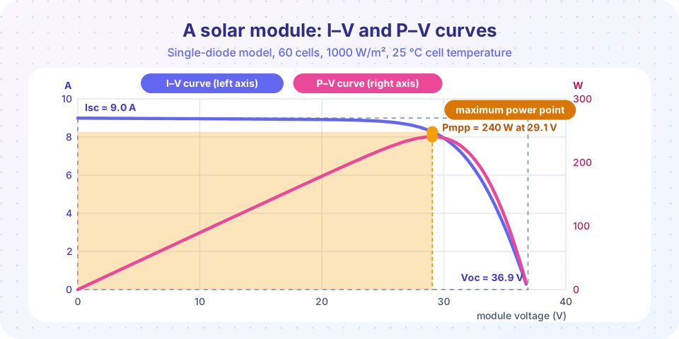
with the diode saturation current I0, the ideality factor n, the thermal voltage Vt = kT/q (about 26 mV), the series resistance Rs and the shunt resistance Rsh. The equation is implicit in I, so it is solved numerically (Newton's method converges in a few steps). The module of the figure and the examples below has Ns = 60, Iph = 9 A, I0 = 1e-7 A, n = 1.3, Rs = 0.3 Ω, Rsh = 300 Ω, and gives:
| Quantity | Value |
|---|---|
Voc |
36.9 V |
Isc |
9.0 A |
Vmpp, Impp |
29.1 V, 8.27 A |
Pmpp |
240 W |
FF |
0.72 |
Observe the shape. For V well below Voc the current is almost constant at Isc, so power grows linearly with voltage. Near the knee the current starts to fall quickly, then collapses. The product V·I therefore has a single, rather broad, maximum. A useful rule of thumb is Vmpp ≈ 0.78 to 0.82 × Voc; here it is 0.79.
Irradiance and temperature
- Irradiance.
Iscis proportional toG: at 20 % of full sun the short-circuit current is 20 % as large.Vocfalls only logarithmically (a few percent for a five-fold reduction), soVmppbarely moves and the MPP power scales almost withG. - Temperature. A hotter cell has a larger
I0, which lowersVocby about−0.3 % per °Cfor crystalline silicon, whileIscrises slightly (about+0.05 % per °C). The net effect is that power drops about0.35 to 0.45 %for every degree above 25 °C. A module in the desert at 65 °C cell temperature gives roughly 15 % less than its nameplate rating.
Both effects mean the MPP moves, so a fixed operating point wastes energy. The controller must follow it.
Steering the operating point with a boost converter
A converter between the module and the load makes the module see a different resistance than the load's. For an ideal boost converter with duty cycle D:
Vpv = (1 − D) · Vout Ipv = Iout / (1 − D) Rin = Vpv / Ipv = (1 − D)² · RL
Changing D therefore moves the operating point along the I-V curve. The MPP is reached when Rin = Vmpp / Impp (3.51 Ω here). For a 48 V DC output with a 9.6 Ω equivalent load, (1 − D)² = 3.51 / 9.6, so D = 0.395. The boost stage is the MPPT converter of nearly every string inverter. A boost can only raise voltage, so the array voltage must stay below the DC link, which is why arrays are wired as strings of many modules in series (hundreds of volts).
Perturb and observe
The simplest tracking algorithm needs no model of the panel:
- Measure
VandI, computeP. - Perturb the operating voltage by a small step
ΔV(for example 0.5 V) in some direction. - Measure the new power. If it increased, keep going in the same direction; if it decreased, reverse.
The operating point climbs the P-V curve and then oscillates by one or two steps around the peak. Small steps reduce the steady-state oscillation but track more slowly; large steps do the opposite. Incremental conductance uses the fact that at the MPP dP/dV = 0, i.e. dI/dV = −I/V, and compares the measured slopes, so it can tell when it has arrived and avoid wandering in changing light. Many products also scan the whole curve periodically to escape local maxima that appear when parts of a string are shaded, because partial shading creates a P-V curve with several peaks.
From module to grid
A grid-tied inverter has two jobs after the MPPT stage:
- Convert the DC link to AC with an inverter (Chapters 5 and 6): single-phase H-bridge for homes, three-phase bridge for larger systems.
- Inject current in phase with the grid voltage. A phase-locked loop (PLL) tracks the grid's phase; a current controller makes the injected current sinusoidal. An LCL filter removes the switching ripple.
Because single-phase power pulsates at twice the grid frequency (p(t) = Vm·Im·(1 − cos 2ωt)/2) while the array delivers constant power, a capacitor in the DC link must absorb that 100 or 120 Hz ripple: the largest, shortest-lived part of the inverter. Grid codes also require the inverter to disconnect within a fraction of a second if the grid disappears (anti-islanding), to keep current distortion below a few percent, and increasingly to ride through grid faults and support voltage.
Typical architectures:
- String inverter: one MPPT per string of series modules; 3 to 100 kW; the standard rooftop choice.
- Central inverter: megawatt units in utility plants.
- Microinverter (one per module) or DC power optimizer (a DC-DC converter per module): MPPT per module, so shade on one module does not drag down the others.
Efficiencies are high: peak values of 97 to 99 % are common, thanks to wide-bandgap devices and the fact that the MPPT boost is lightly loaded in voltage ratio.
Common misconceptions
"The maximum power point is at the highest current." Maximum current (short circuit) delivers zero power; so does maximum voltage (open circuit). The peak is in between.
"A solar inverter just converts DC to AC." Its most important job on the DC side is tracking the MPP; its most important job on the AC side is injecting clean, synchronized current.
"Cold weather is bad for solar panels." Cold raises Voc and power; the opposite of heat. System designers must make sure that a cold morning's high Voc does not exceed the inverter's maximum input voltage.
Try it
The first example computes the module curves with Newton's method for several irradiances and two cell temperatures, and prints Voc, Isc, Pmpp and the fill factor. The temperature dependence uses the standard saturation-current scaling with a silicon band gap of 1.12 eV; the model is illustrative and does not describe a particular product.
Press Run (or Ctrl + Enter) to see the result here.
Program input · what you'd type while the program runs
Type the answers before you press Run, one per line. Each time the program reads a line (with input()), it gets the next line from this box.
The second example simulates perturb-and-observe MPPT on this module. The irradiance drops from 1000 to 400 W/m² halfway through; the tracker follows the moving peak. It models the algorithm acting on the static curve, ignoring converter dynamics.
Press Run (or Ctrl + Enter) to see the result here.
Program input · what you'd type while the program runs
Type the answers before you press Run, one per line. Each time the program reads a line (with input()), it gets the next line from this box.
The third example is an MPPT game. A boost converter feeds a 9.6 Ω load (equivalent to 240 W at 48 V). Move the duty cycle and the irradiance, and watch the operating point on the curve. Try to reach 100 % of the available power.
Check your understanding
Quick check · 5 questions
of 5 answered You scored / 5 · perfect!
-
1. A module has Voc = 40 V, Isc = 10 A and Pmpp = 300 W. What is the fill factor?
FF = 300 / (40 × 10) = 0.75. -
2. A boost converter feeds a 100 Ω load. At D = 0.8 what resistance does the module see?
Rin = (1 − D)² RL = 0.04 × 100 = 4 Ω. -
3. How does a rise in cell temperature change a module's open-circuit voltage?
A hotter junction has a larger saturation current, which lowers Voc. -
4. What does perturb and observe do?
It climbs the P-V curve by trial, reversing when power falls. -
5. Why does a single-phase grid-tied inverter need a large DC-link capacitor?
AC power pulsates at 2f while the array delivers constant power; the capacitor buffers the difference.
Summary
- A module follows the single-diode equation; its I-V curve is a nearly constant current that falls at
Voc, soP = V·Ihas one peak (typicallyVmpp ≈ 0.8 Voc). Iscis proportional to irradiance;Vocfalls about 0.3 %/°C, so power falls about 0.4 %/°C above 25 °C.- A boost converter sets
Rin = (1 − D)²·RL; perturb and observe steers it to the MPP. - Grid-tied inverters add a PLL, a current controller and an LCL filter, and need a DC-link capacitor for the 2f pulsation.
Track your progress
Create a free account to tick off lessons and pick up where you left off on any device.
of Power Electronics lessons completed