


















Lesson 26 of 45 · Control and Modulation
Chapter 6 overview: control and modulation
See how feedback and modulation turn a switching circuit into a regulated converter: PWM, harmonics, small-signal models, voltage-mode and current-mode control.
A converter built from switches does exactly what its gate signals tell it to do. Left alone it will not hold its output voltage when the load changes or the input sags, and the raw waveform it makes is full of harmonics. Two ideas fix both problems. Modulation decides how the switches are driven so that the average output is what you want. Feedback control adjusts that drive continuously to hold the output where you want it, despite disturbances.
This chapter gives you both ideas, and the mathematics that keeps the feedback loop from becoming an oscillator.
What you will learn
- Describe the two roles of control in a converter: shaping the waveform and holding the output.
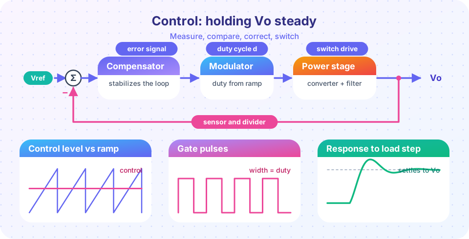
- Name the building blocks of a feedback loop and where each sits.
- See why a loop that is too aggressive turns unstable.
- Know what each lesson of the chapter covers.
Key terms
Modulation: the rule that converts a control signal into switch on and off times.
Duty cycle (d): the fraction of each switching period in which a switch conducts.
Compensator: the circuit or code that shapes the loop's response so that it is stable and fast.
Crossover frequency: the frequency at which the loop gain falls to one (0 dB).
Phase margin: how far the loop's phase is from the unstable value (−180°) at crossover.
The big picture
Two jobs for control
The loop
This chapter
Modulation: where to switch
The simplest modulator compares a control voltage vc with a ramp (a sawtooth or triangle) of constant frequency and amplitude Vramp. The switch turns on at the start of each period and turns off when the ramp crosses vc. The resulting duty cycle is d = vc / Vramp. Feed in a constant vc and you get a DC converter with a fixed output; feed in a sine and you get an inverter whose output average follows the sine: that is sinusoidal PWM, the first topic of this chapter.
Feedback: how much to switch
A fixed duty cycle gives the right output only if the input voltage and the load never change and the converter has no losses. In reality the output drifts. A feedback loop measures the output, subtracts it from a reference, and lets a compensator change the duty cycle until the error vanishes. The compensator is where the design work happens: too little gain and the output is slow and inaccurate; too much and the loop oscillates. The control engineer's task is to pick gain and phase so that the loop is fast and stable, which is the subject of the lessons on small-signal modeling and current-mode control.
Your route through the chapter
- PWM and sinusoidal PWM: carriers, modulation index, harmonics, third-harmonic injection and dead-time errors.
- Voltage-mode control and small-signal models: the buck's
LCresonance, Bode plots, compensators, crossover and phase margin. - Current-mode control: the inner current loop, cycle-by-cycle limiting and slope compensation.
- Chapter 6 review: a recap table, a design calculator and a ten-question quiz.
Common misconceptions
"More loop gain is always better." Gain gives accuracy and speed, but the power stage adds delay and an LC resonance. Past a limit the loop oscillates.
"PWM and feedback are the same thing." PWM is the actuator: it turns a number into pulses. Feedback is the logic that chooses the number.
Try it
The first example is an averaged simulation of a 12 V to 5 V buck converter with a small parasitic resistance. Without feedback the output sags when the load current doubles; a PI controller restores it. It is a simulation of the averaged circuit equations, not of individual switching cycles.
Press Run (or Ctrl + Enter) to see the result here.
Program input · what you'd type while the program runs
Type the answers before you press Run, one per line. Each time the program reads a line (with input()), it gets the next line from this box.
The second example shows why gain has a limit. A sampled integral controller drives a value x toward a target with the rule x[n+1] = x[n] + K·(target − x[n]). Move the gain K: below 1 the approach is smooth, between 1 and 2 it overshoots and rings, above 2 it grows without bound. A real loop with delay behaves the same way.
Check your understanding
Quick check · 4 questions
of 4 answered You scored / 4 · perfect!
-
1. A ramp modulator has Vramp = 2 V. A control voltage of 0.5 V gives what duty cycle?
d = vc / Vramp = 0.5 / 2 = 0.25. -
2. What does the compensator do?
The compensator is the part of the loop that you design. -
3. Why can too much loop gain be harmful?
Beyond a limit the phase margin disappears and the output oscillates. -
4. Which block turns a number into switch pulses?
The modulator (comparator and ramp) converts the control signal into a duty cycle.
Summary
- Control has two jobs: modulation shapes the pulses, feedback holds the output.
- A PWM modulator compares a control signal with a ramp, so
d = vc / Vramp. - A feedback loop measures, compares, compensates and modulates; its gain and phase must be chosen for stability.
- The next lessons cover PWM waveforms, voltage-mode small-signal design and current-mode control.
Next: PWM and sinusoidal PWM
Track your progress
Create a free account to tick off lessons and pick up where you left off on any device.
of Power Electronics lessons completed