


















Lesson 31 of 45 · Magnetics and Thermal Design
Chapter 7 overview: magnetics and thermal design
See why inductors, transformers and heat set the physical limits of every power converter, and how the lessons on cores, windings and thermal paths fit together.
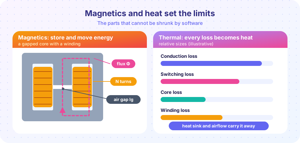
You can change a converter's control law with a keystroke, but you cannot change the size of its inductor or the temperature of its transistor with software. Two physical facts decide how small, light, efficient and reliable a power converter can be. The first is that energy must be stored and moved by magnetic components, and they saturate. The second is that every watt lost becomes heat, and silicon fails when it gets too hot.
This chapter teaches you to size an inductor, to wind a transformer that does not saturate, and to follow the heat from a transistor junction out to the air. These are calculations, not mysteries: a handful of equations carry you through most designs.
What you will learn
- Explain why inductors and transformers dominate the size of many converters.
- Name the three limits in magnetic design: saturation, losses and window space.
- Describe the thermal chain from junction to ambient.
- Know what each lesson of the chapter covers.
Key terms
Core: the magnetic material (usually ferrite, powder or steel) that guides the flux.
Saturation: the flux density at which the core can no longer increase its flux, so the inductance collapses.
Core loss: energy lost as heat in the core material every cycle (hysteresis and eddy currents).
Copper loss: I²R in the winding, increased by the skin and proximity effects at high frequency.
Thermal resistance (θ): the temperature rise per watt along a heat path, in °C/W.
The big picture
Two physical limits
Magnetic design asks
Thermal design asks
Why magnetics set the size
Look inside any switching power supply and the largest, heaviest parts are the inductor and the transformer. This is not an accident. The energy a converter must store per cycle is ½ L I², and the flux density is limited to a few tenths of a tesla before the core saturates. A given core can only hold so much energy, so to handle more power you need a bigger core or a higher switching frequency. That is the main reason silicon-carbide and gallium-nitride devices, which allow higher frequencies, shrink converters so effectively: the magnetics get smaller.
Why heat sets the limit
Every converter has an efficiency below 100 %. A 98 % efficient 1 kW converter still loses 20 W, enough to burn a finger if nothing carries the heat away. The temperature of the semiconductor junction (typically limited to 125 to 175 °C) decides the maximum power. Thermal design is the art of keeping the junction below that limit for the longest, hottest day the product will see.
Your route through the chapter
- Inductor design covers the gapped core, the turns and gap calculation, saturation, skin effect and losses.
- Transformer design applies Faraday's law, the area-product method and leakage inductance.
- Thermal design builds the loss budget and the thermal resistance chain to find the junction temperature.
- Chapter 7 review offers a recap table, a combined design tool and a ten-question quiz.
Common misconceptions
"A bigger inductance is always better." Past a point the winding and the core grow, the resistance and the cost rise, and the transient response slows.
"Efficiency 98 % means 2 % of the heat does not matter." In absolute watts it matters a great deal, and efficiency often drops at high temperature.
Try it
The first example shows where the energy of a gapped inductor really sits. For the core of the previous figure it computes the energy stored in the ferrite and in the air gap for the same flux density. It is a calculation with the standard energy-density formula B²/(2µ).
Press Run (or Ctrl + Enter) to see the result here.
Program input · what you'd type while the program runs
Type the answers before you press Run, one per line. Each time the program reads a line (with input()), it gets the next line from this box.
The second example is a first look at the thermal chain you will study in detail: enter the power loss and the thermal resistances and read the junction temperature. It uses Tj = Ta + P·(θJC + θCS + θSA).
Check your understanding
Quick check · 4 questions
of 4 answered You scored / 4 · perfect!
-
1. Why do inductors and transformers dominate the size of many converters?
Energy stored per volume is limited by the saturation flux density. -
2. A 500 W converter is 96 % efficient. How much heat does it produce at full load?
Input power is 500/0.96 = 521 W, so the loss is about 21 W (roughly 20 W). -
3. Which equation gives junction temperature in a simple steady-state model?
The temperature rises above ambient by power times thermal resistance. -
4. What makes higher switching frequency attractive for magnetics?
The core only has to handle the energy or volt-seconds of one short period.
Summary
- Magnetics and heat are the hard limits of converter design: cores saturate and junctions overheat.
- Energy storage is limited by flux density, so more power needs a bigger core or a higher frequency.
- Every loss ends up as heat;
Tj = Ta + P·θties the loss budget to the junction temperature. - The chapter covers inductors, transformers and thermal design in that order.
Next: Inductor design
Track your progress
Create a free account to tick off lessons and pick up where you left off on any device.
of Power Electronics lessons completed