


















Lesson 35 of 45 · Magnetics and Thermal Design
Chapter 7 review: magnetics and thermal design
Review gapped inductors, Faraday's law, area product, core and copper loss, thermal resistance and heat sinks with a recap table, a combined design tool and a ten-question quiz.
This chapter covered the two physical limits that no control law can remove. Magnetic components store and move energy but saturate and lose energy in the core and the winding. Heat flows from the junction to the ambient across a chain of thermal resistances, and the junction must stay cool. The recap below collects the equations; the worked design afterwards uses all of them together on one converter.
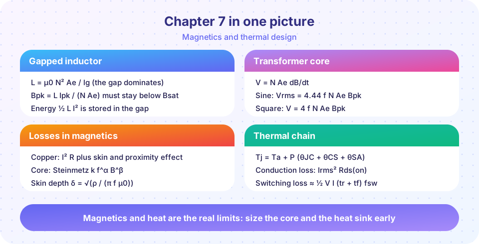
Recap table
| Topic | Key result | Lesson |
|---|---|---|
| Gapped inductor | L = µ0 N² Ae / lg; energy ½ L I² sits in the gap |
Inductor design |
| Turns | N = L·Ipk / (Bmax·Ae); Bpk = L·Ipk / (N·Ae) |
same |
| Saturation | ferrite 0.3 to 0.4 T when hot; powder cores soft and higher | same |
| Skin depth | δ = √(ρ/(π f µ0)), about 0.24 mm for hot copper at 100 kHz |
same |
| Core loss | Pv = k f^α B^β; at fixed voltage Pv ∝ f^(α−β) |
same |
| Faraday | v = N Ae dB/dt; 4.44 f N Ae Bpk (sine), 4 f N Ae Bpk (square) |
Transformer design |
| Area product | Ap ≥ Pin / (2 f Bpk J Ku) for square-wave drive |
same |
| Flux walking | volt-second imbalance accumulates as DC flux | same |
| Conduction loss | Irms² · Rds(on)(Tj) |
Thermal design |
| Switching loss | ½ V I (tr + tf) fsw |
same |
| Thermal chain | Tj = Ta + P (θJC + θCS + θSA) |
same |
| Heat sink | θSA ≤ (Tj,max − Ta)/P − θJC − θCS |
same |
One converter, all three calculations
Take the 48 V to 12 V, 20 A buck at 200 kHz from the thermal lesson.
- Ripple and inductor.
D = 0.25. Allow 30 % ripple:ΔIL = 6 A.L = (Vin − Vo)·D / (fsw·ΔIL) = 36 × 0.25 / (2e5 × 6) = 7.5 µH. Peak currentIpk = 20 + 3 = 23 A. - Magnetics. On a core with
Ae = 150 mm²andBmax = 0.3 T:N = 7.5e-6 × 23 / (0.3 × 150e-6) = 3.8 → 4 turns; the gap isµ0 × 16 × 150e-6 / 7.5e-6 = 0.40 mm. The peak flux density is0.29 T. - Winding. At
5 A/mm²the wire needs4 mm²; four turns of 70 mm mean length give about1.6 mΩ, soP ≈ 0.6 Wof copper loss. - MOSFET. From the thermal lesson, about 5.4 W at 125 °C; with
θJC = 1,θCS = 0.5the sink must beθSA ≤ 12.4 °C/Wat 50 °C ambient.
The calculator below repeats the whole chain for any converter.
Try it
The first example is a design chain: from the converter specification it calculates the inductance, the turns, the gap, the peak flux density, the winding loss and the MOSFET junction temperature. It uses the formulas of the chapter with simple assumptions.
Press Run (or Ctrl + Enter) to see the result here.
Program input · what you'd type while the program runs
Type the answers before you press Run, one per line. Each time the program reads a line (with input()), it gets the next line from this box.
The second example is a flashcard drill for the chapter's equations. Click a card to flip it and test whether you remember each formula before reading it.
Check your understanding
Quick check · 10 questions
of 10 answered You scored / 10 · perfect!
-
1. A gapped inductor has N = 12 turns, Ae = 100 mm² and a gap of 1 mm. What is L (gap only)?
L = 4πe-7 × 144 × 100e-6 / 1e-3 = 18.1 µH. -
2. A 22 µH inductor carries 8 A peak on a core with Ae = 70 mm². With Bmax = 0.25 T, how many turns?
N = 22e-6 × 8 / (0.25 × 70e-6) = 10.06, rounded up to 11. -
3. Where does most of the energy of a gapped inductor reside?
The gap has the highest reluctance and therefore holds most of the field energy. -
4. A 100 kHz, square-wave transformer winding has V = 100 V, Ae = 100 mm² and Bpk = 0.1 T. How many turns?
N = 100 / (4 × 1e5 × 100e-6 × 0.1) = 25. -
5. Doubling the frequency at a fixed voltage (the flux swing halves) changes the Steinmetz core loss by about (α = 1.5, β = 2.6)
2^1.5 × 0.5^2.6 = 2.83 × 0.165 = 0.47. -
6. Which is the maximum allowed θSA for P = 12 W, Ta = 40 °C, Tj,max = 120 °C, θJC = 0.8 and θCS = 0.4 °C/W?
θSA ≤ 80/12 − 1.2 = 5.47 °C/W. -
7. What limits Bpk in a 100 kHz ferrite transformer?
Core loss grows steeply with flux swing and frequency, so loss sets Bpk well below saturation. -
8. What is flux walking?
Unbalanced volt-seconds integrate into a DC flux that can saturate the core. -
9. A solid wire is 2 mm thick at 100 kHz in a hot winding (δ ≈ 0.24 mm). What is the best remedy for high AC resistance?
Thin strands let the current use the whole cross-section. -
10. The junction is 20 °C above the case at 10 W. What is θJC?
θJC = ΔT / P = 20 / 10 = 2 °C/W.
Summary
- Gapped inductors:
L = µ0N²Ae/lg,N = L·Ipk/(Bmax·Ae); the energy sits in the gap. - Transformers:
v = N·Ae·dB/dt; flux swing from volt-seconds; area product chooses the core; mind flux walking and leakage. - Losses: copper (skin and proximity), core (
k f^α B^β), conduction and switching. - Thermal:
Tj = Ta + P·θ; choose the heat sink fromθSA ≤ (Tj,max − Ta)/P − θJC − θCSand iterate when losses depend on temperature. - Next, we put all the pieces to work in real applications.
Track your progress
Create a free account to tick off lessons and pick up where you left off on any device.
of Power Electronics lessons completed