


















Lesson 6 of 45 · Power Semiconductors
Chapter 2 Overview: The Power Semiconductor Map
Overview of power semiconductors: diodes, MOSFETs, IGBTs, thyristors, SiC and GaN, with a map of voltage, current and frequency ranges and what each device is for.
A power converter is only as good as its switches. In this chapter you meet the devices that do the switching, learn what each one does well and badly, and build the habit of choosing a device from three numbers: voltage it must block, current it must carry and frequency at which it must switch. By the end of the chapter you should be able to read a datasheet and say which losses to expect.
What you will learn
- The main families of power semiconductors and where each is used.
- Which ratings decide whether a device fits a design.
- What the rest of the chapter covers.
Key terms
- Blocking voltage: the largest voltage a device can withstand in the off state.
- Current rating: how much current it can carry continuously without overheating.
- Controlled switch: a device that can be turned on, and possibly off, by a control signal.
- Wide bandgap (WBG): semiconductors such as SiC and GaN with a larger energy gap than silicon.
Uncontrolled, semi-controlled and fully controlled devices
Power semiconductors split into three groups by how much control you have:
- Uncontrolled (diodes): conduct when forward biased and block when reverse biased. You cannot control them. They are the basic rectifying element.
- Semi-controlled (thyristors, SCRs): you can turn them on with a gate pulse, but they turn off only when the current falls to zero. Used where power is huge and the circuit itself provides current zero crossings, such as line-commutated rectifiers.
- Fully controlled (MOSFET, IGBT, GaN HEMT, GTO, IGCT): you can turn them on and off by a gate signal. These make modern PWM converters possible.
Diodes
MOSFETs
IGBTs
Thyristors
SiC and GaN
The three numbers
Voltage. Choose a device that blocks comfortably more than the highest voltage it will see, including spikes. A rule of thumb: 1.5 to 2 times the DC bus voltage for a 400 V bus (for example a 650 V or 1200 V device on a 400 V link, depending on switching spike margin).
Current. The device must carry the highest rms and peak current without exceeding its junction-temperature limit. Current rating on its own is not enough; thermal resistance and cooling decide the real limit.
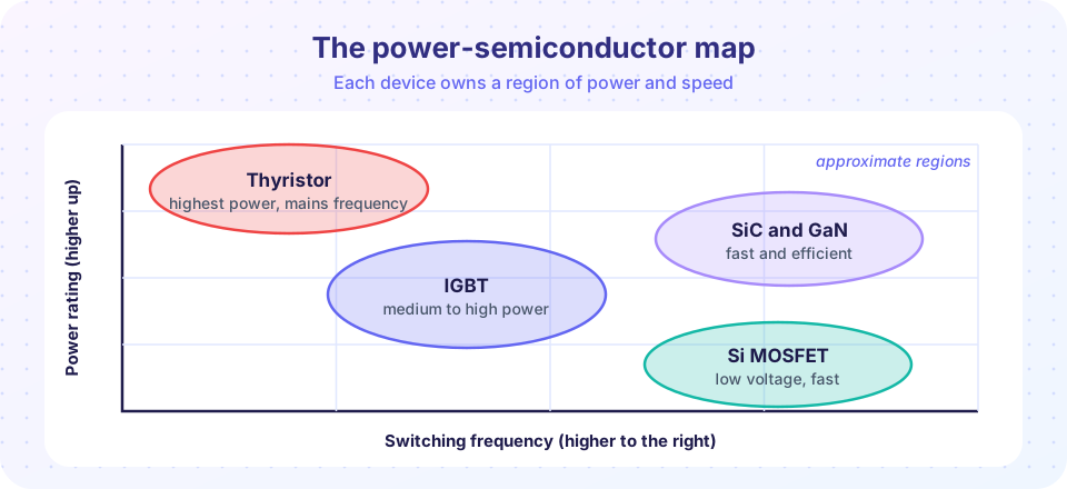
Frequency. Switching losses increase with frequency, so every device has a practical limit. Thyristors work at mains frequency, IGBTs typically up to tens of kHz, silicon MOSFETs up to a few hundred kHz and wide-bandgap devices up to several hundred kHz or MHz.
What each lesson covers
- Power diodes: PN, Schottky, forward drop and reverse recovery.
- Power MOSFETs: conduction, gate charge, body diode and ratings.
- IGBTs, thyristors and wide-bandgap devices: where silicon runs out of steam and what SiC and GaN bring.
- Chapter 2 review: the turn-on overlap picture and a long quiz.
Common misconceptions
- "A bigger current rating always means a better device." A device rated for more current often has bigger gate and output capacitance, so it switches more slowly and loses more at high frequency.
- "GaN and SiC replace silicon everywhere." Silicon still wins on cost, availability and ruggedness for many mains-frequency and low-cost designs.
Try it
The map in the picture is qualitative. The plot below draws approximate commercial voltage-current ranges for five device families on log axes. Values are rounded and vary by manufacturer: treat them as a feel for the territory, not as limits.
Press Run (or Ctrl + Enter) to see the result here.
Program input · what you'd type while the program runs
Type the answers before you press Run, one per line. Each time the program reads a line (with input()), it gets the next line from this box.
Check your understanding
Quick check · 4 questions
of 4 answered You scored / 4 · perfect!
-
1. Which device cannot be turned on or off by a control signal?
A diode has no gate; its state follows the circuit voltage and current. -
2. A thyristor, once turned on by its gate, turns off when:
Thyristors latch; they stop conducting only when the current drops below the holding current. -
3. Which devices usually dominate megawatt-class line-frequency converters?
Huge ratings and line commutation suit thyristors, as in HVDC and large rectifiers. -
4. Why choose a device voltage rating well above the DC bus voltage?
Parasitic inductances create voltage overshoot when current is switched off, so you need headroom.
Summary
- Power semiconductors are uncontrolled (diodes), semi-controlled (thyristors) or fully controlled (MOSFET, IGBT, GaN).
- Voltage, current and frequency decide the device choice; each family owns a region on the map.
- Margin on voltage and attention to thermal limits matter as much as raw ratings.
Next: Power Diodes
Track your progress
Create a free account to tick off lessons and pick up where you left off on any device.
of Power Electronics lessons completed