


















Lesson 33 of 45 · Magnetics and Thermal Design
Transformer design: Faraday's law, core size and leakage
Design a high-frequency power transformer: Faraday's law, turns from flux swing, the area-product method, flux walking, leakage inductance, isolation and winding layout.
A transformer does two jobs in a power converter: it changes the voltage level by the turns ratio, and it provides galvanic isolation so that a touchable output is separated from the mains. In switched-mode supplies it operates at tens or hundreds of kilohertz, so it is a small, light ferrite component instead of the heavy iron block of a 50 Hz mains transformer. The design question is the same in both cases: how many turns, on which core, so that the core does not saturate and the windings fit and do not overheat?
Everything comes from Faraday's law, which you used in the motor-drive lesson to explain V/f control. Here you turn it into a design recipe.
What you will learn
- Apply
v = N·Ae·dB/dtto find the flux swing and the number of primary turns. - Use
4.44·f·N·Ae·Bpkfor sine waves and4·f·N·Ae·Bpkfor square waves. - Choose a core with the area-product method
Ap = Ae·Aw. - Calculate the secondary turns from the output voltage and duty cycle.
- Explain leakage inductance, flux walking and the safety requirements of an isolating transformer.
Key terms
Magnetizing inductance (Lm): the inductance seen at the primary with the secondary open; it draws the magnetizing current that builds the flux.
Leakage inductance (Lk): the part of the flux that links one winding but not the other; it behaves like a small inductor in series.
Area product (Ap): core area Ae times window area Aw; a measure of the core's power-handling ability.
Flux walking: a gradual DC shift of the flux caused by unbalanced volt-seconds.
Creepage and clearance: the surface and air distances between mains-side and output-side conductors.
Faraday's law as a design equation
The voltage across a winding of N turns around a core of area Ae is
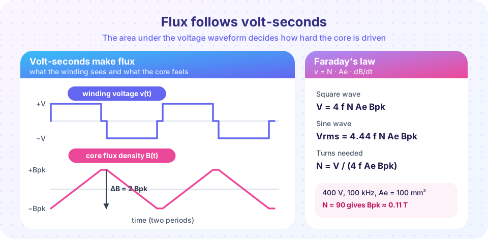
v(t) = N · Ae · dB/dt
so the flux density is the integral of the voltage:
B(t) = (1 / (N·Ae)) ∫ v dt
Inspect the figure. When the voltage is positive, B rises linearly; when it is zero, B stays constant; when it is negative, B falls. The peak-to-peak swing ΔB = 2·Bpk equals the volt-seconds applied divided by N·Ae. For the common waveforms:
sine wave:    Vrms = 4.44 · f · N · Ae · Bpk       (4.44 = 2π/√2)
square wave:  V    = 4    · f · N · Ae · Bpk       (full-duty, amplitude equals rms)
any wave:     N    = V·t_on / (2 · Bpk · Ae)       (t_on: width of one pulse, bipolar drive)
How much flux?
The peak flux density is limited by one of two things:
- At 50/60 Hz (silicon steel): saturation, about 1.2 to 1.7 T.
- At 20 kHz to 500 kHz (ferrite): core loss, not saturation. The Steinmetz loss grows as
B^2.6andf^1.5, so engineers typically chooseBpkof 0.05 to 0.2 T, far below the 0.4 T saturation level.
Example (mains transformer). A 230 V, 50 Hz transformer on a steel core with Ae = 20 cm² and Bpk = 1.2 T needs
N = V / (4.44 · f · Ae · Bpk) = 230 / (4.44 × 50 × 20e-4 × 1.2) = 432 turns
Because the number of turns is inversely proportional to frequency, a transformer at 100 kHz needs 2,000 times fewer turns for the same core size (if the same flux density were used), which is why a switched-mode supply is so small.
Choosing the core: the area product
Power flows only if the winding window has room for copper. Each winding carries current I through N turns, and the window area Aw must hold all of them. If the primary may use half the window with fill factor Ku and current density J:
Np · Irms = J · Ku · Aw / 2
and the primary voltage is V = 4 f Np Ae Bpk (square wave). Multiplying the two, the number of turns cancels:
V · I = 2 · f · Bpk · J · Ku · Ae · Aw → Ap = Ae · Aw ≥ Pin / (2 · f · Bpk · J · Ku)
For a sine-wave drive, replace the 2 by 2.22. Worked example: a 500 W full-bridge converter at f = 100 kHz, Bpk = 0.1 T, J = 4 A/mm² = 4×10⁶ A/m² and Ku = 0.3:
Ap ≥ 500 / (2 × 1e5 × 0.1 × 4e6 × 0.3) = 2.08e-8 m⁴ = 2.08 cm⁴
You choose from the manufacturer's tables a core with a larger area product, for instance one with Ae = 125 mm².
Turns and ratio
With that core and a 400 V DC input driving a full bridge with each pulse lasting 90 % of the half period (t_on = 4.5 µs):
Np = V · t_on / (2 · Bpk · Ae) = 400 × 4.5e-6 / (2 × 0.1 × 125e-6) = 72 turns
The output is a rectified bipolar pulse train with an average of Vin · (Ns/Np) · 0.9. For a 48 V output with a 1 V diode drop: Ns = 49 × 72 / (400 × 0.9) = 9.8 → 10 turns (per half of a center-tapped secondary). The turns ratio is therefore 72:10.
Leakage, isolation and layout
Leakage inductance arises because not all flux links both windings. It is typically 0.5 to 3 % of the magnetizing inductance. In a flyback converter its energy ½·Lk·Ipk² cannot be passed to the secondary and creates a voltage spike at turn-off, which a snubber or clamp must absorb: a direct loss of efficiency. To reduce leakage, interleave the windings (primary half, secondary, primary half) and wind each layer tightly and completely across the bobbin.
Proximity loss grows with the number of layers; thin foil or Litz wire and fewer layers reduce it.
Safety isolation. A transformer between mains and a touchable output must satisfy safety standards: reinforced insulation, triple-insulated wire or margin tape, creepage and clearance distances of several millimetres, and a high-voltage test of about 3 kV. These are not engineering preferences but legal requirements for mains products.
Flux walking. In a full-bridge or push-pull converter, a small mismatch between the positive and negative volt-seconds adds a DC component to the flux. The winding resistance only slowly removes it, so the flux creeps upward cycle after cycle until the core saturates and the magnetizing current explodes. Remedies: a series DC-blocking capacitor on the primary, peak-current-mode control (which forces equal peaks), and symmetrical drive.
Flyback transformers are different. A flyback "transformer" is really a coupled inductor: it stores energy in an air gap in one phase and releases it in the next. You design it like the gapped inductor of the previous lesson, with the added turns ratio and leakage considerations.
Common misconceptions
"A transformer transfers power through the core by storing it." An ideal transformer transfers energy continuously, storing none; only the magnetizing and leakage inductances store a little. A flyback is the exception because it is a coupled inductor.
"Increase the frequency and nothing changes except size." Core loss, proximity loss, switching loss and leakage effects all change with frequency; the optimum is usually at 50 to 500 kHz.
"Saturation only matters for the inductor." A transformer saturates if the volt-seconds are too large, or if DC builds up in the flux; both can destroy the switches.
Try it
The first example carries out the 500 W design: it computes the area product, the turns, the secondary turns and the flux waveform for the bipolar pulse drive. It is a calculation with the formulas above.
Press Run (or Ctrl + Enter) to see the result here.
Program input · what you'd type while the program runs
Type the answers before you press Run, one per line. Each time the program reads a line (with input()), it gets the next line from this box.
The second example demonstrates flux walking. It models the magnetizing branch with a saturating inductance (i = (λ0/Lm)·sinh(λ/λ0)) and a winding resistance, and drives it with a balanced and with a slightly unbalanced bridge. It is a simplified model that shows the mechanism, not a prediction for a real core.
Press Run (or Ctrl + Enter) to see the result here.
Program input · what you'd type while the program runs
Type the answers before you press Run, one per line. Each time the program reads a line (with input()), it gets the next line from this box.
The third example is a turns calculator for sine and square drive. Enter the voltage, frequency, core area and flux density.
Check your understanding
Quick check · 5 questions
of 5 answered You scored / 5 · perfect!
-
1. A 230 V, 50 Hz transformer uses a core with Ae = 15 cm² and Bpk = 1.3 T. How many primary turns?
N = 230 / (4.44 × 50 × 15e-4 × 1.3) = 531. -
2. A square-wave transformer at 100 kHz has a 48 V winding, Ae = 60 mm² and Bpk = 0.1 T. How many turns?
N = 48 / (4 × 1e5 × 60e-6 × 0.1) = 20 turns. -
3. Why is the peak flux density of a 100 kHz ferrite transformer typically much lower than saturation?
Steinmetz loss goes as f^α B^β; the loss limit, not saturation, sets Bpk. -
4. What is flux walking?
Unbalanced volt-seconds integrate into a growing DC flux that can saturate the core. -
5. How does interleaving the windings help?
Interleaving makes the windings couple more tightly so less flux leaks.
Summary
- Faraday's law
v = N·Ae·dB/dtlinks volt-seconds to flux:N = V·t_on / (2·Bpk·Ae), orV = 4.44 f N Ae Bpk(sine) and4 f N Ae Bpk(square). - At high frequency the flux density is limited by core loss, not by saturation.
- The area product
Ap ≥ Pin / (2 f Bpk J Ku)finds a core that can handle the power. - Secondary turns follow from the output voltage and duty cycle; leakage inductance, flux walking and safety isolation are the practical problems.
Next: Thermal design
Track your progress
Create a free account to tick off lessons and pick up where you left off on any device.
of Power Electronics lessons completed