


















Lesson 20 of 45 · DC-DC Converters
Chapter 4 Review: DC-DC Converters
Review chapter 4: gain, inductor ripple, capacitor ripple and CCM boundary for the buck, boost and buck-boost converters, a design helper and a ten-question quiz.
You have met the three basic DC-DC converters and seen how one rule, volt-second balance, derives their gains. This page collects the design equations in one picture and one table, lets you try a design helper, and ends with a chapter test.
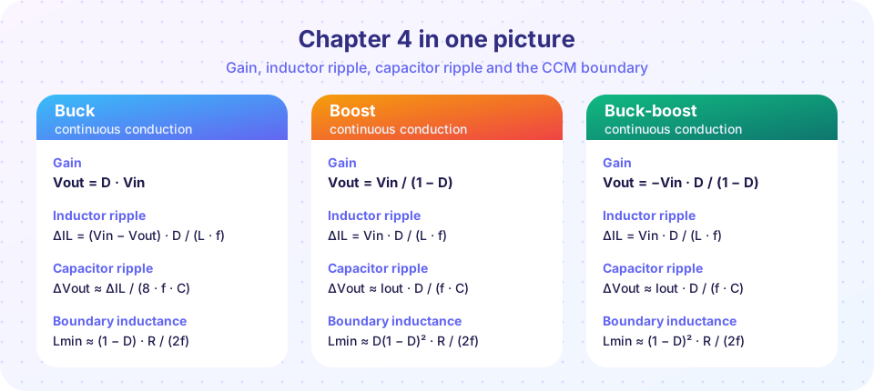
Chapter in one paragraph
A DC-DC converter chops its input with a switch and uses an inductor and a capacitor to average the pulses. In continuous conduction, volt-second balance gives Vout = D Vin for the buck, Vin/(1 − D) for the boost and −Vin D/(1 − D) for the buck-boost. The inductor ripple ΔIL comes from the voltage across it during the on time, divided by L fsw; the output ripple comes from the capacitor absorbing the ripple (buck) or the pulsed diode current (boost, buck-boost). Below the critical inductance, the converter enters DCM and the gain depends on the load.
Recap table
| Item | Buck | Boost | Buck-boost |
|---|---|---|---|
Gain Vout/Vin |
D |
1/(1 − D) |
−D/(1 − D) |
Average IL |
Iout |
Iout/(1 − D) |
Iout/(1 − D) |
Inductor ripple ΔIL |
(Vin − Vout) D/(L f) |
Vin D/(L f) |
Vin D/(L f) |
Capacitor ripple ΔV |
ΔIL/(8 f C) |
Iout D/(f C) |
Iout D/(f C) |
| Switch voltage stress | Vin |
Vout |
Vin plus the magnitude of Vout |
Critical L |
(1 − D) R/(2f) |
D(1 − D)² R/(2f) |
(1 − D)² R/(2f) |
| Input current | pulsed | smooth | pulsed |
| Output current | smooth | pulsed | pulsed |
Revisit the lessons: Buck, Boost and Buck-boost.
A design recipe you can reuse
- Find the duty cycle from the gain formula.
- Choose the inductor ripple, typically 20% to 40% of the average inductor current.
- Compute
Lfrom the ripple formula. Pick the next standard value. - Compute the peak inductor current and choose a saturation current above it, with margin.
- Compute
Cfrom the output ripple spec, then check the ESR contribution. - Check device voltage and current ratings, and the CCM boundary at the lightest load.
- Estimate the losses (chapter 1): conduction, switching, magnetics.
Try it
The helper below applies the recipe to all three topologies for specs of your choice. It uses the ideal formulas, including the 30% ripple rule for the inductor, so treat the output as a starting point.
Press Run (or Ctrl + Enter) to see the result here.
Program input · what you'd type while the program runs
Type the answers before you press Run, one per line. Each time the program reads a line (with input()), it gets the next line from this box.
Check your understanding: chapter test
Quick check · 10 questions
of 10 answered You scored / 10 · perfect!
-
1. A buck runs from 48 V and must supply 12 V. What duty cycle (ideal) is required?
D = Vout / Vin = 12 / 48 = 0.25. -
2. A boost from 9 V must give 36 V. What duty cycle is required?
D = 1 − Vin/Vout = 1 − 0.25 = 0.75. -
3. Which converter has a smooth input current?
In the boost the inductor is in series with the input, so the input current is continuous. -
4. Vin = 24 V, Vout = 12 V, L = 20 µH, fsw = 300 kHz. What is the buck inductor ripple?
D = 0.5, ΔIL = (24 − 12) × 0.5 / (20e-6 × 300e3) = 6 / 6 = 1 A. -
5. What is the average inductor current in a boost delivering 2 A at D = 0.6?
IL = Iout / (1 − D) = 2 / 0.4 = 5 A. -
6. What voltage must the switch of a buck-boost with Vin = 15 V and Vout = −15 V withstand (ideal)?
Vin + |Vout| = 30 V, before adding margin for spikes. -
7. Why does the buck-boost invert the output polarity in the basic circuit?
The inductor's top terminal is pulled below ground when the switch opens, so the output node is negative. -
8. What happens to the output of an open-loop buck in DCM as the load gets lighter?
In DCM the gain rises above D as the load current drops, so feedback is needed. -
9. Doubling the switching frequency at the same ripple lets you do what to L and C?
ΔIL ∝ 1/(L f) and ΔV ∝ 1/(f C) for a fixed ripple budget. -
10. A designer wants a 12 V rail from a battery that varies between 9 V and 16 V. Which topology is the most natural choice?
The output lies within the input range, so the converter must both step up and step down.
Summary
- One rule, volt-second balance, derives all three gains.
- Ripple formulas follow from the inductor voltage in each state; sizes scale as
1/fsw. - Compare topologies by gain, input and output current shape, and switch stress.
- Keep CCM at the lightest load you care about, or design for DCM on purpose.
- Chapter 5 turns to inverters: making AC from DC.
Track your progress
Create a free account to tick off lessons and pick up where you left off on any device.
of Power Electronics lessons completed