


















Lesson 22 of 45 · Inverters and Motor Drives
Single-phase inverters: half bridge and full bridge
Build a single-phase inverter from switch legs: half-bridge and H-bridge, square-wave output, harmonics and THD, dead time, shoot-through and phase-shift control.
Every inverter starts with the same tiny building block: two switches in series across a DC supply, with the output taken from the point between them. That is a leg. Understanding what one leg can and cannot do, and then how two legs combine into an H-bridge, gives you everything you need to read a three-phase inverter in the next lesson.
In this lesson you will derive the voltages a half bridge and a full bridge can produce, calculate the harmonics of the simplest output (a square wave), and meet the two most important practical details: dead time and shoot-through.
What you will learn
- Describe the switching states of a half bridge and an H-bridge and the output voltage in each.
- Calculate the rms value, fundamental amplitude and THD of a square wave.
- Explain dead time, shoot-through and the role of the antiparallel diodes.
- Use phase-shift control to vary the output of a full bridge and remove the 3rd harmonic.
Key terms
Half bridge: one leg across a split DC link; the load connects to the midpoint of the two capacitors.
Full bridge (H-bridge): two legs; the load connects between the two midpoints.
Shoot-through: both switches of one leg on at once, which shorts the DC link.
Dead time: a short delay with both switches off that protects against shoot-through.
THD (total harmonic distortion): the rms of all harmonics divided by the rms of the fundamental.
One leg, two states
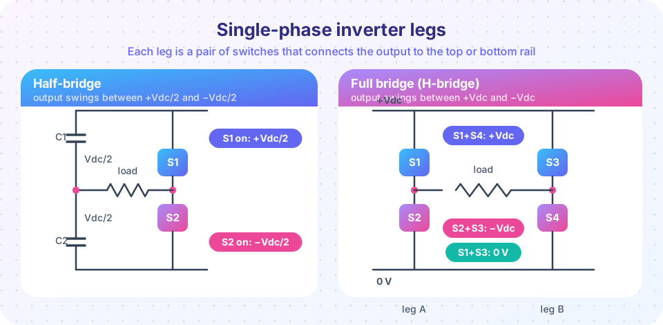
A leg has an upper switch S1 and a lower switch S2 between the rails +Vdc and 0. The midpoint is connected to the positive rail when S1 conducts and to the negative rail when S2 conducts. Never both: that would short-circuit the supply.
A half bridge splits the DC link with two equal capacitors, each holding Vdc/2, and connects the load between the leg's midpoint and the capacitor midpoint. With S1 on, the load sees +Vdc/2; with S2 on, it sees −Vdc/2. The half bridge is cheap (two switches) but the output is only half the DC link.
A full bridge uses two legs. The load sits between the two midpoints, so the voltage is the difference of the two leg voltages:
| S1 | S2 | S3 | S4 | Output vAB |
|---|---|---|---|---|
| on | off | off | on | +Vdc |
| off | on | on | off | −Vdc |
| on | off | on | off | 0 (freewheeling through the top) |
| off | on | off | on | 0 (freewheeling through the bottom) |
For the same DC link the full bridge delivers twice the output voltage, so a resistive load receives four times the power, at the cost of four switches. Each switch still blocks only Vdc, which is why the full bridge is the standard choice above a few hundred watts.
The square-wave output
The simplest control is to alternate the two active states every half period: +Vdc for T/2, then −Vdc for T/2. The waveform has these properties:
average value        = 0
rms value            = Vdc            (the voltage is always ±Vdc)
fundamental, peak    V1 = 4·Vdc / π ≈ 1.273 · Vdc
fundamental, rms     V1,rms = 0.9003 · Vdc
n-th harmonic, peak  Vn = V1 / n      (n = 3, 5, 7, … only)
The Fourier series of a symmetric square wave contains only odd harmonics because of its half-wave symmetry, and their amplitudes fall like 1/n. That slow decay is the weakness of the square wave: the 3rd harmonic is a third as large as the fundamental.
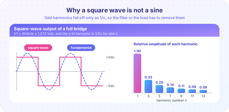
The total harmonic distortion follows from the rms values. The total rms is Vdc; the fundamental rms is 0.9003 Vdc. Because rms values of orthogonal components add in squares,
THD = √(Vrms² − V1,rms²) / V1,rms = √(1 − 0.8106) / 0.9003 = 0.483 (48.3 %)
So a square wave carries almost half as much harmonic content as fundamental. For a motor this is tolerable because the winding inductance limits the current harmonics (Ih = Vh / (2π·h·f·L)); for a household appliance it is not, which is why PWM (Chapter 6) replaced pure square waves.
How big must the DC link be?
If you want a sine with rms 230 V, its peak is 230·√2 = 325 V. A PWM full bridge can only make a sine whose peak does not exceed the DC link, so it needs Vdc ≥ 325 V in practice somewhat more. A square-wave bridge needs only Vdc = 230 / 0.9003 = 255 V for a fundamental of 230 V rms, but delivers the 48 % THD. The DC link voltage is a design decision with consequences.
Dead time, shoot-through and the diodes
Real switches do not turn off instantly. A MOSFET or IGBT needs tens to hundreds of nanoseconds to stop conducting. If the controller commands S2 on at the same moment it commands S1 off, both can conduct briefly and a huge current flows through the DC link: shoot-through. The cure is a deliberate dead time td (typically 0.2 to 2 µs for MOSFETs and IGBTs) in which both switches of a leg are off.
But what happens to the load current during dead time? An inductive load cannot change its current instantly. It continues to flow, and it needs a path: the antiparallel diode (MOSFETs have a body diode; IGBT modules include a co-packaged one). If the current was flowing out of the leg, the diode of the lower switch picks it up and the output sits at the negative rail until the next switch turns on; if it was flowing in, the diode of the upper switch conducts.
Two consequences follow:
- Dead time makes the output voltage depend on the direction of the load current. At small current the error voltage is about
Vdc·td·fswper leg, which distorts low-amplitude sines (a topic for the modulation chapter). - The diodes also carry reactive current, so they must be rated for it. A bridge feeding a purely inductive load has the diodes conducting half of the time.
Gate drivers for bridge legs usually have an interlock that makes shoot-through impossible even if the microcontroller makes a mistake, plus a programmable dead time. Never rely on software alone.
Controlling the amplitude: phase shift
A square wave has a fixed amplitude, 4Vdc/π. To control it without changing the DC link, let both legs switch as 50 % square waves but delay the second leg by a phase shift α. The output vAB = vA − vB is then +Vdc for an angle α, zero for 180° − α, then −Vdc for α and zero again. So α is the width of each voltage pulse.
V1  = (4·Vdc/π) · sin(α/2)
Vn  = (4·Vdc/(n·π)) · sin(n·α/2)     (n odd)
At α = 180° the legs are in antiphase and you recover the full square wave; at α = 0 both legs are identical and the output is zero. Look at the third harmonic: sin(3α/2) = 0 when α = 120°. Pulses 120° wide (with 30° zero intervals either side) therefore eliminate the 3rd harmonic while still delivering V1 = 1.273·Vdc·sin 60° = 1.103·Vdc. This is the simplest example of selective harmonic elimination, an idea you will meet again.
Common misconceptions
"A full bridge can be turned on in any combination." Turning on both switches of one leg is a short circuit of the DC link. The four allowed combinations are the four rows of the table.
"The antiparallel diodes are only protection." They are an active part of the circuit: with inductive loads they carry current during every dead time and during part of each cycle.
"A square wave is a bad idea everywhere." For loads that filter by themselves (motors, heating, some transformers) a square-wave or quasi-square-wave inverter is cheap and efficient.
Try it
The first example computes the harmonics of the full-bridge square wave with an FFT and compares them with the formula 4/(nπ). It also calculates THD from the rms values.
Press Run (or Ctrl + Enter) to see the result here.
Program input · what you'd type while the program runs
Type the answers before you press Run, one per line. Each time the program reads a line (with input()), it gets the next line from this box.
The second example sweeps the phase shift α of a full bridge from 0° to 180° and measures the fundamental and the third harmonic. It confirms V1 = (4/π)sin(α/2) and shows the third harmonic vanishing at 120°.
Press Run (or Ctrl + Enter) to see the result here.
Program input · what you'd type while the program runs
Type the answers before you press Run, one per line. Each time the program reads a line (with input()), it gets the next line from this box.
The third example is a switch explorer for the full bridge. Click the four switches and see the output voltage, or a warning when you create a shoot-through. It models ideal switches only.
Check your understanding
Quick check · 5 questions
of 5 answered You scored / 5 · perfect!
-
1. A full bridge is fed from Vdc = 300 V and runs as a square-wave inverter. What is the amplitude of its fundamental?
V1 = 4·Vdc/π = 4 × 300 / 3.1416 = 382 V. -
2. Which statement about the harmonics of a symmetric square wave is correct?
Half-wave symmetry removes even harmonics; the odd ones have amplitude V1/n. -
3. Why is a dead time inserted between turning one switch of a leg off and the other on?
Switches turn off slowly; overlap would short the DC link (shoot-through). -
4. In a phase-shifted full bridge, voltage pulses 120° wide (leg shift α = 120°) remove which harmonic?
Vn is proportional to sin(nα/2), which is zero for n = 3 and α = 120°. -
5. For the same DC link, how does the full bridge compare with the half bridge?
The half bridge swings ±Vdc/2, the full bridge ±Vdc.
Summary
- A leg connects the output to the positive or negative rail; never turn both switches on.
- A half bridge swings
±Vdc/2; a full bridge swings±Vdcand also offers a zero state. - A square wave has
V1 = 4Vdc/π, odd harmonicsV1/nand THD of 48.3 %. - Dead time prevents shoot-through; the antiparallel diodes carry the inductive current meanwhile.
- Phase-shift control varies the fundamental as
sin(α/2)and removes the 3rd harmonic atα = 120°.
Track your progress
Create a free account to tick off lessons and pick up where you left off on any device.
of Power Electronics lessons completed