


















Lesson 11 of 45 · Rectifiers and AC-DC Conversion
Chapter 3 Overview: From Mains AC to DC
Overview of rectifiers and AC-DC conversion: half-wave, full-wave, filtered, three-phase and controlled rectifiers, with performance measures like form factor and ripple factor.
Electric utilities deliver alternating current, but almost everything electronic needs direct current. The rectifier is the first stage of countless products: phone chargers, TVs, computers, battery chargers, electric-vehicle chargers, and the front end of industrial motor drives. In this chapter you learn the main rectifier circuits, how to smooth their output with a capacitor, how three-phase and controlled rectifiers work, and how to judge a rectifier's performance with a few simple numbers.
What you will learn
- The main rectifier circuits and when each is used.
- The measures used to compare rectifiers: average value, rms value, form factor and ripple factor.
- Why a rectifier also affects the grid, through power factor and harmonics.
- What the rest of the chapter covers.
Key terms
- Average (DC) value: the mean of the output voltage over one cycle.
- Form factor: rms value divided by average value of the output.
- Ripple factor: the ratio of the AC part of the output to its DC part,
RF = √(FF² − 1). - Peak inverse voltage (PIV): the highest reverse voltage a diode must withstand.
- Power factor: real power divided by apparent power drawn from the supply.
Why rectify?
Half or full wave
Smooth it
Go three-phase
Measures of rectifier performance
Take an output voltage v(t) with period T. Define:
- Average:
Vavg = (1/T) ∫ v dt - Rms:
Vrms = √((1/T) ∫ v² dt) - Form factor:
FF = Vrms / Vavg - Ripple factor:
RF = Vac / Vavg = √(FF² − 1)
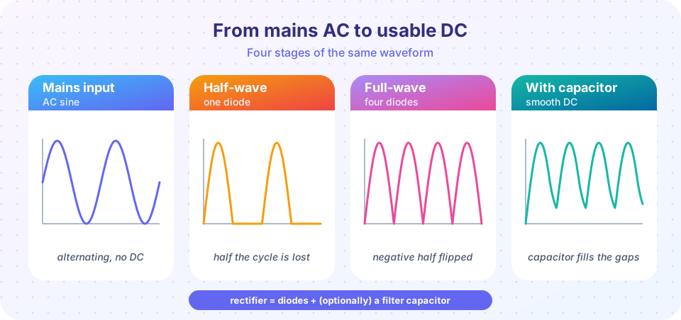
For a perfect DC level, FF = 1 and RF = 0. For an ideal half-wave rectified sine with peak Vpk: Vavg = Vpk/π ≈ 0.318 Vpk, Vrms = Vpk/2, FF = 1.571 and RF = 1.211. For full-wave: Vavg = 2 Vpk/π ≈ 0.637 Vpk, Vrms = Vpk/√2 ≈ 0.707 Vpk, FF = 1.111 and RF = 0.483. A ripple factor of 0.48 is still huge, which is why a filter capacitor is almost always needed.
The ladder of circuits
- Half-wave: one diode; simple, but the output is poor and the transformer core is magnetized by DC.
- Full-wave center-tapped and bridge: both half-cycles are used; the bridge needs no center tap.
- Filtered (capacitor-input): a capacitor after the bridge fills the gaps; typical for small supplies.
- Three-phase six-pulse bridge: six diodes on three phases, ripple at six times the mains frequency, used for industrial loads.
- Controlled rectifiers: thyristors replace diodes, and the firing angle
αcontrols the average output.
Impact on the supply
A rectifier with a large filter capacitor draws current only near the voltage peaks, in short, tall pulses. That current is rich in harmonics, and the power factor of such a supply is often only 0.5 to 0.7, even though it appears to be a simple resistive load. Regulations limit this for larger products, so many supplies add power-factor correction (PFC), usually a boost converter after the bridge. We meet PFC again in later chapters.
What each lesson covers
- Single-phase rectifiers: half-wave, center-tapped and bridge circuits with worked numbers.
- Capacitor filters: ripple, conduction angle and why peaks are tall.
- Three-phase and thyristor rectifiers: six-pulse bridge and firing angle control.
- Chapter 3 review: a comparison table and a ten-question quiz.
Common misconceptions
- "Rectified output is DC." It is unidirectional, but it still has a large ripple at multiples of the mains frequency, until a filter or a high pulse number cleans it up.
- "A rectifier is a resistive load." A capacitor-input rectifier draws current in pulses, so the grid sees a nonlinear load.
Try it
Use the ideal waveforms to check the numbers in this lesson. The program computes average, rms, form factor and ripple factor numerically for half-wave and full-wave rectified sine waves, so you can see them match the formulas above. It models ideal diodes and no filter.
Press Run (or Ctrl + Enter) to see the result here.
Program input · what you'd type while the program runs
Type the answers before you press Run, one per line. Each time the program reads a line (with input()), it gets the next line from this box.
Check your understanding
Quick check · 4 questions
of 4 answered You scored / 4 · perfect!
-
1. What is the ideal average of a full-wave rectified sine of peak 100 V?
Vavg = 2 Vpk / π = 63.7 V. -
2. What is the form factor of a pure DC voltage?
For DC the rms equals the average, so the ratio is 1 and the ripple factor is 0. -
3. Why does a capacitor-input rectifier have a poor power factor?
Short current pulses are rich in harmonics, so apparent power exceeds real power. -
4. Which rectifier has the highest ripple frequency for a 50 Hz supply?
A six-pulse bridge makes six pulses per cycle, 300 Hz at 50 Hz, which is easiest to filter.
Summary
- Rectifiers convert AC to DC; their output is unidirectional but rippled.
- Measure with average, rms, form factor
FFand ripple factorRF = √(FF² − 1). - Half-wave:
0.318 Vpk, RF 1.21. Full-wave:0.637 Vpk, RF 0.48. More pulses means less ripple. - Filter capacitors help the load but hurt the supply's power factor.
Next: Single-Phase Rectifiers
Track your progress
Create a free account to tick off lessons and pick up where you left off on any device.
of Power Electronics lessons completed