


















Lesson 32 of 45 · Magnetics and Thermal Design
Inductor design: cores, gaps, saturation and losses
Design a gapped power inductor: energy in the gap, turns from peak flux density, gap length from L = μ0N²Ae/lg, saturation, skin effect, Litz wire and core loss.
An inductor is the energy bucket of a switching converter. In a buck converter it stores energy while the switch is on and delivers it while the switch is off; its size and quality decide the current ripple, the efficiency and often the whole volume of the converter. Designing one is surprisingly systematic: three equations, an understanding of saturation, and a feel for losses are enough to get from specification to winding.
In this lesson you will design a 47 µH, 10 A inductor from scratch and discover why a power inductor has an air gap in its core.
What you will learn
- Derive
L = µ0·N²·Ae / lgfor a gapped core and explain why the gap stores the energy. - Calculate the number of turns from
Bpk = L·Ipk / (N·Ae)and the gap length. - Describe saturation and compare ferrite, powder and other core materials.
- Estimate copper loss including skin effect, and choose strand diameter or Litz wire.
- Explain core loss with the Steinmetz equation and how frequency changes it.
Key terms
Ae: the effective cross-sectional area of the core through which the flux passes.
Air gap (lg): a deliberate break in the magnetic path that stores most of the energy.
Bsat: the saturation flux density; for power ferrite roughly 0.3 to 0.4 T at operating temperature.
Skin depth (δ): the depth at which AC current density falls to 37 % in a conductor; for copper δ ≈ 66 mm / √f (f in Hz) at 20 °C.
Litz wire: a bundle of thin insulated strands, each thinner than the skin depth, to reduce AC resistance.
From magnetic circuit to inductance
A magnetic core works like a circuit in which flux Φ plays the role of current. The magnetomotive force N·I drives the flux through the reluctance ℜ of the path:
N · I = Φ · ℜ                ℜ = l / (µ · A)
L = N · Φ / I = N² / ℜ
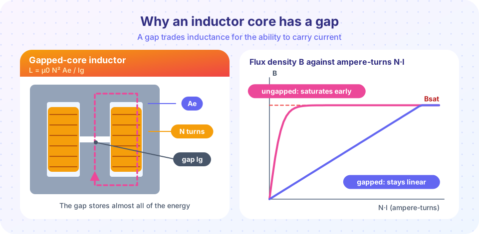
A core of high permeability (µr = 2,000 for typical power ferrite) has a tiny reluctance, so the inductance would be enormous (1.07 mH for 16 turns on the example core below) and the core would saturate at only half an ampere. Insert an air gap of length lg: its reluctance lg / (µ0·Ae) is far larger than the core's, and it dominates the circuit:
ℜ ≈ lg / (µ0 · Ae) → L = µ0 · N² · Ae / lg
Two things follow. First, the inductance is nearly set by N, Ae and lg, almost independent of the core's µr, which varies with temperature and from part to part. Second, the flux density in the gap, B = µ0·N·I / lg, is proportional to the current right up to the point where the core saturates, which now happens at a far higher current.
The energy ½ L I² equals the energy density B²/(2µ0) times the volume of the gap Ae·lg. Check it: with L = µ0N²Ae/lg and B = µ0NI/lg, B²/(2µ0)·Ae·lg = µ0N²I²Ae/(2lg) = ½ L I². The air gap really does hold the energy.
The design procedure
Given the inductance L and the peak current Ipk (the DC current plus half the ripple), choose a core with area Ae and a maximum flux density Bmax below saturation (leave margin: 0.25 to 0.3 T for ferrite).
- Turns.
N = L · Ipk / (Bmax · Ae), rounded up. - Gap.
lg = µ0 · N² · Ae / L(reduce a little for fringing, which adds effective area). - Check the flux.
Bpk = L · Ipk / (N · Ae). - Check the winding fits. The wire area is
Irms / J, whereJ(the current density) is about 3 to 6 A/mm² for natural cooling. All turns must fit in the core's window with insulation and bobbin allowances; a fill factor of 0.3 to 0.4 is typical. - Estimate losses and temperature (below). If the temperature rise exceeds 40 K, go to a bigger core or lower the flux.
Worked example. L = 47 µH, Ipk = 10 A, Bmax = 0.3 T, Ae = 100 mm²:
N  = 47e-6 × 10 / (0.3 × 100e-6) = 15.7  →  16 turns
lg = 4πe-7 × 16² × 100e-6 / 47e-6 = 0.68 mm
Bpk = 47e-6 × 10 / (16 × 100e-6)  = 0.294 T
The gap holds ½ × 47e-6 × 10² = 2.35 mJ.
Materials
- Ferrite (MnZn): low loss up to hundreds of kHz,
Bsatabout 0.3 to 0.5 T, brittle, saturates abruptly (hard saturation). Needs a discrete gap. - Powdered iron, MPP, Kool-Mu and similar powder cores: magnetic particles in an insulating binder give a distributed air gap.
Bsatabout 0.7 to 1.5 T, lower permeability (tens to hundreds) and soft saturation (inductance falls gradually). Higher core loss than ferrite at high frequency. - Nanocrystalline and amorphous alloys:
Bsatabout 1.2 T, very high permeability, used for high-power and high-frequency chokes. - Silicon steel laminations:
Bsat1.5 to 2 T, used at 50/60 Hz.
Saturation
When the flux density approaches Bsat the permeability collapses toward that of air. A hard-saturating ferrite inductor behaves like a short circuit after saturation: the current spikes and the switch can be destroyed. Always design the peak current, including overload and start-up, below the saturation limit and verify it at the highest temperature, because Bsat of ferrite falls from about 0.5 T at 25 °C to 0.4 T at 100 °C.
Winding loss and the skin effect
At low frequency the wire's resistance is Rdc = ρ·l / A and the copper loss is Irms²·Rdc. At 100 kHz the current crowds into a thin layer at the surface of the conductor (the skin effect) and in neighbouring layers the field of one turn pushes current in the next (the proximity effect). The skin depth is
δ = √( ρ / (π · f · µ0) ) ≈ 0.24 mm for copper at 100 kHz and 100 °C
A solid wire thicker than about 2δ wastes its centre. The remedies are several parallel thin strands (Litz wire), flat foil, or fewer layers. Use strands with a diameter below δ and the AC resistance stays close to the DC resistance.
Core loss
Cores lose energy every cycle through hysteresis and eddy currents. The empirical Steinmetz equation describes it:
Pv = k · f^α · B^β (loss per unit volume)
Typical ferrite values are α about 1.3 to 1.8 and β about 2.3 to 3. The exponent of the flux swing β is larger than the exponent of frequency α. In a converter running at a fixed voltage, raising the frequency lowers the flux swing in proportion (ΔB ∝ 1/f), so core loss changes as f^(α−β) and falls. Higher frequency lowers core loss and core size but raises switching loss and skin-effect copper loss.
Common misconceptions
"The inductance of a gapped inductor is set by the core material." It is set mainly by the gap. That is the point of the gap.
"A bigger air gap always means a better inductor." A bigger gap needs more turns for the same inductance, raising copper loss, and the fringing field near the gap heats nearby windings.
"Saturation just reduces inductance a bit." In a hard-saturating ferrite core inductance can fall by ten times or more within a small current increase.
Try it
The first example designs the 47 µH inductor and then uses a nonlinear magnetic-circuit model to plot how its inductance falls with current, compared with the same core without a gap. The core material is modeled by a smooth saturation curve (B = Bsat·tanh(µ0·µi·H / Bsat)); this is a model, not manufacturer data, and it includes the core's own reluctance, so the small-signal value comes out about 4 % below the gap-only formula.
Press Run (or Ctrl + Enter) to see the result here.
Program input · what you'd type while the program runs
Type the answers before you press Run, one per line. Each time the program reads a line (with input()), it gets the next line from this box.
The second example covers losses. It computes the AC-to-DC resistance ratio of round copper wires at 100 kHz using the exact Bessel-function solution for an isolated wire, shows why thin strands win, and then scales the core loss with the Steinmetz equation. The Steinmetz exponents are typical, not those of a particular material.
Press Run (or Ctrl + Enter) to see the result here.
Program input · what you'd type while the program runs
Type the answers before you press Run, one per line. Each time the program reads a line (with input()), it gets the next line from this box.
The third example is a skin-depth and strand calculator. Choose the frequency and winding temperature; it reports the skin depth and the largest strand diameter that keeps the AC resistance close to DC, plus the number of 0.1 mm strands needed to match a given copper area.
Check your understanding
Quick check · 5 questions
of 5 answered You scored / 5 · perfect!
-
1. A gapped inductor has N = 20 turns, Ae = 80 mm² and a gap of 0.5 mm. What is its inductance (gap-dominated)?
L = µ0 N² Ae / lg = 4πe-7 × 400 × 80e-6 / 0.5e-3 = 80.4 µH. -
2. Where is most of the energy of a gapped inductor stored?
The gap has by far the largest reluctance, so most of the magnetic energy sits there. -
3. An inductor must carry 8 A peak with L = 100 µH on a core with Ae = 120 mm². Using Bmax = 0.25 T, how many turns are needed?
N = L·Ipk / (Bmax·Ae) = 100e-6 × 8 / (0.25 × 120e-6) = 26.7, rounded up to 27. -
4. At 100 kHz the skin depth of hot copper is about 0.24 mm. Which strand diameter is best for the winding?
Strands thinner than the skin depth keep the AC resistance close to the DC resistance. -
5. With a fixed input voltage, what happens to core loss if the switching frequency is doubled?
Pv ∝ f^α B^β with B ∝ 1/f gives f^(α−β), which decreases because β is larger than α.
Summary
- A gap makes
L = µ0 N² Ae / lg, stores the energy in the gap and lets the core carry much more current before saturating. - Design:
N = L·Ipk/(Bmax·Ae),lg = µ0 N² Ae / L, checkBpkand that the wire fits. - Ferrite saturates hard near 0.3 to 0.4 T; powder cores saturate softly at higher flux density.
- Skin and proximity effects raise winding loss at high frequency; use strands thinner than
δ(Litz wire) or foil. - Core loss follows
k f^α B^β; at constant voltage, a higher frequency reduces core loss but raises other losses.
Next: Transformer design
Track your progress
Create a free account to tick off lessons and pick up where you left off on any device.
of Power Electronics lessons completed